Self-compensating magnetoelastic torque sensor system

a self-compensation and magnetoelastic torque technology, applied in the field of magnetic sensors, can solve the problems of unambiguous variables in b, impractically expensive, and inability to eliminate non-uniform external magnetic flux sources, and achieve the effect of low manufacturing cost and ease of us

Inactive Publication Date: 2011-08-23
WENG WENSHENG
View PDF26 Cites 29 Cited by
  • Summary
  • Abstract
  • Description
  • Claims
  • Application Information

AI Technical Summary

Benefits of technology

[0017]The present invention was devised to provide a magnetoelastic torque transducer that can overcome the aforementioned problems, and one object of the invention is providing a torque transducer having high reliability.
[0019]A further object of the present invention is to provide a magnetoelastic torque transducer that can compensate for temperature offset.
[0023]An additional object of the present invention is to provide a magnetoelastic torque transducer which symmetry matches the sensitivity of paired magnetic flux B sensors electrically so that a complete common mode rejection can be accomplished.
[0025]Alternatively, a passive field sensor (or sensors) can be placed proximate to the active magnetoelastic zone with lower field strength than that of active field sensor to partially compensate the rotational dependent signal and temperature sensitivity drift.
[0027]The invention permits lower manufacturing cost and ease of use as compared with the prior transducer technology, and the sensor system is robust enough for most harsh environments.

Problems solved by technology

The basic weakness in these prior art approaches to magnetoelastic torque transducers is that they can not distinguish whether the sensed quantity, i.e., magnetic flux B, is depended on torsional stress induced by applied torque or an external magnetic flux source, or a temperature dependent magnetic flux, thus with the undesirable result that the sensed variations in B do not unambiguously indicate a variation in torque.
This configuration can not eliminate non-uniform external magnetic flux sources, known as near field, such as a nearby electric motor, or a nearby moving ferromagnetic object.
Unfortunately, providing sufficient space for the requisite shield and counteracting coils has created practical problems in applications where space is at a premium, also, such a shield appears to be impractically expensive for using on highly cost-competitive devices, such as in automotive applications, and these approaches increase the complexity and the cost of a complete sensor while also generally reducing its adaptability, maintainability and reliability.
These approaches also do not compensate for the temperature offset effect and rotation-dependent output.

Method used


Image

  • Self-compensating magnetoelastic torque sensor system
  • Self-compensating magnetoelastic torque sensor system
  • Self-compensating magnetoelastic torque sensor system

Examples


Embodiment Construction

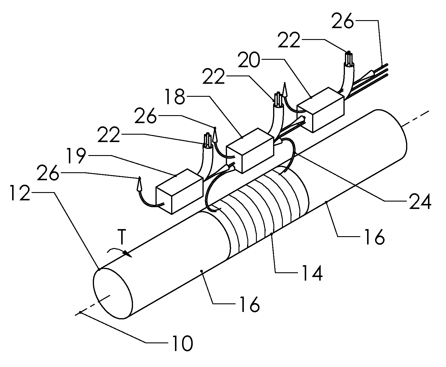
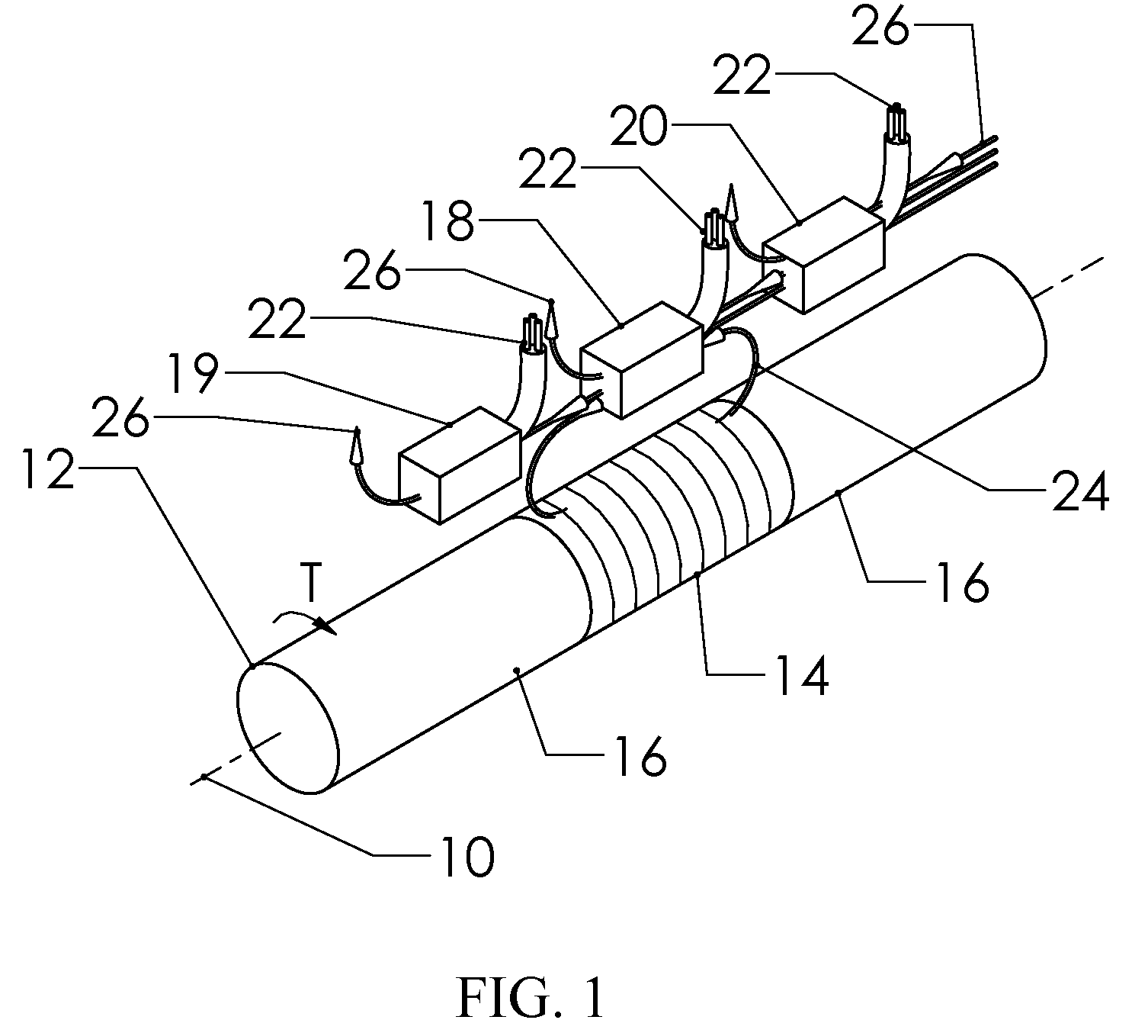
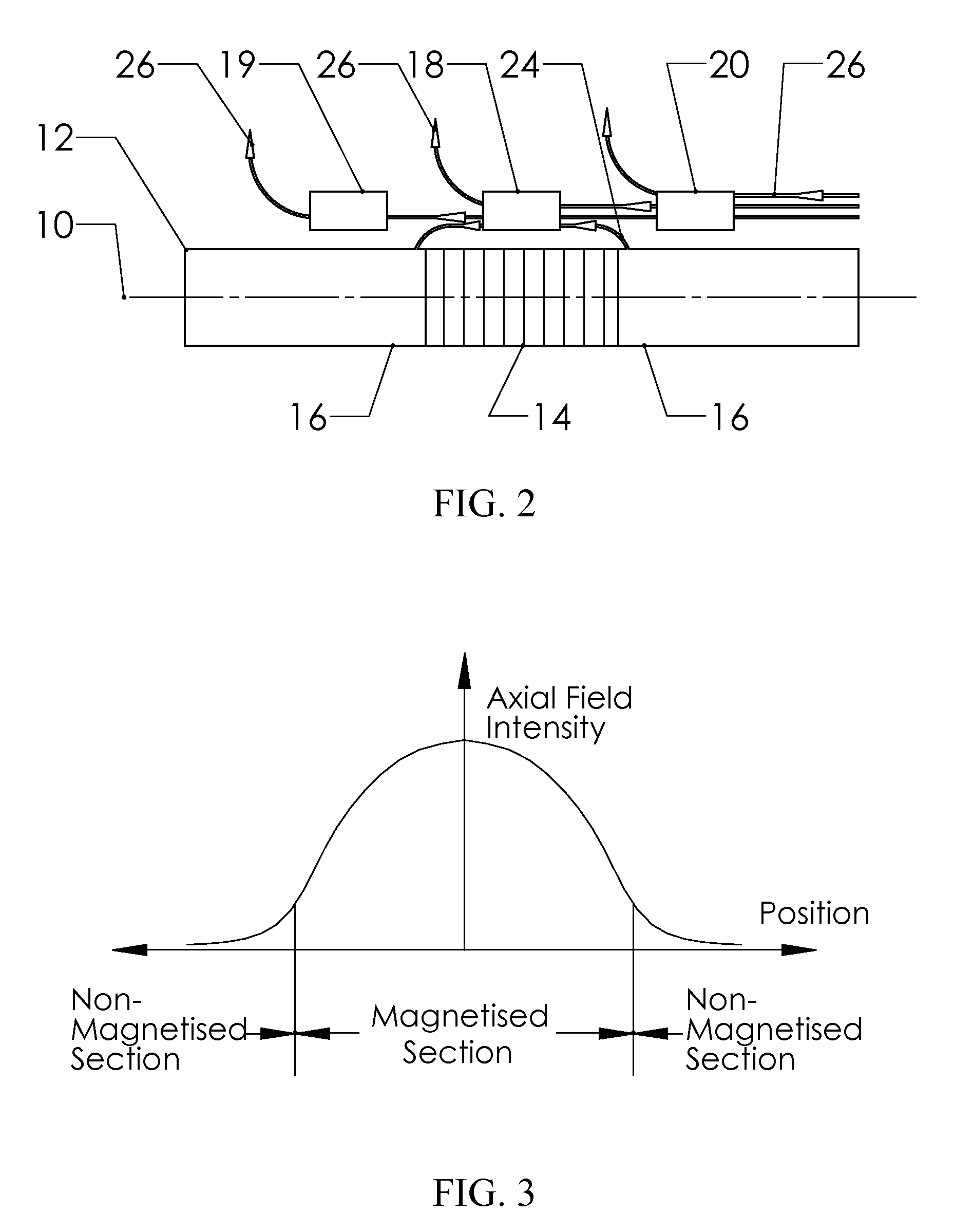
[0034]FIGS. 1 and 2 illustrate a preferred embodiment of a polarized band based torque sensing apparatus in accordance with the present invention. In this exemplary embodiment, the torque carrying shaft 12, having a torque T applied about a central longitudinal axis 10, has an magnetoelastically active portion 14 and at least one magnetic passive area 16 (e.g., a non-magnetized section). At least one active field sensor 18 is placed proximate to the magnetoelastically active portion 14 to detect the magnetic flux 24 arising from the applied torque, and at least one passive field sensor, 19 or 20, is placed on either side of the active field sensor 18, wherein the passive field sensors 19 and 20 are disposed in such a way that they are far away enough from the magnetoelastically active portion 14 to avoid the magnetic flux 24 dependent on the applied torque T.

[0035]FIG. 3 shows axial magnetic field strength arises from the applied torque T across the magnetoelastic active zone 14, th...


PUM

PropertyMeasurementUnit
angleaaaaaaaaaa
torqueaaaaaaaaaa
magnetoelasticaaaaaaaaaa

Abstract

A magnetic torque transducer arrangement for self-compensating effects of external magnetic sources and temperature offset includes a shaft with at least one magnetized zone, at least one active magnetic field sensor and at least one passive magnetic field sensor disposed in such a way that the active field sensor is always in a position with higher magnetic field strength arising from applied torque than that of the passive sensor. Passive field sensors may also be placed on both sides of the active field sensor, or on only one side of the active field sensor. The transducer output is obtained by subtracting the output of the passive field sensors from that of the active field sensor, thus canceling out the effect of the interfering magnetic field flux and temperature offset on the torque transducer, and partially filtering out the temperature sensitivity drift and rotational dependant signal.

Description

CROSS-REFERENCE TO RELATED APPLICATIONS[0001]Not ApplicableFEDERALLY SPONSORED RESEARCH[0002]Not ApplicableSEQUENCE LISTING OR PROGRAM[0003]Not ApplicableBACKGROUND OF THE INVENTION[0004]1. Field of the Invention[0005]This invention relates to the field of using magnetic sensors to measure torque applied to a rotatable shaft. More particularly, the invention relates to the particular placement of magnetic field sensors in relation to a magnetic transducer element to measure the torque applied to a shaft, and the sensor system is immune to external magnetic sources within a large temperature range.[0006]2. Prior Art[0007]Magnetic torque sensors are known in the art. Many versions of this type of magnetoelastic torque sensor have been proposed and described in a plurality of publications and patent specifications. There are two general ways of utilizing the magnetoelastic phenomenon as the sensing mechanism for a non-contacting torque sensor. One is permeability based, and the other i...

Claims


Application Information

Patent Timeline
Patent Type & Authority Patents(United States)
IPC IPC(8): G01L3/02
CPCG01L3/102G01R33/063G01R33/18G01L3/105
Inventor WENG, WENSHENG
Owner WENG WENSHENG
Why Eureka
Try Eureka