Liquid separation device

Inactive Publication Date: 2006-10-24
DA PERIGON
View PDF14 Cites 2 Cited by
  • Summary
  • Abstract
  • Description
  • Claims
  • Application Information

AI Technical Summary

Benefits of technology

[0014]A diaphragm bow is formed with a number of bow slats, preferably evenly distributed about the longitudinal axis of the diaphragm bow. The bow slats are designed to be resiliently braced in against the central rodlike body of the diaphragm bow, so as to allow the device to be displaced through a pipe having a relatively small internal diameter. When the diaphragm bow reaches the site of use, thus leaving the lead-in pipe, the bow slats assume a braced position in which they abut the inside of a pipe that is to be filled with grouting compound, and which has a relatively large internal diam

Problems solved by technology

When the grouting compound, which is slightly more viscous and has a higher density than drill fluid, is introduced at the desired location in the well, there is a considerable risk that the grouting compound may sink into the drill fluid and as a result end up in the wrong place in the well.
Another danger is that it will be diluted by the drill fluid, and therefore not form a satisfactory casting.
In addition to being relatively costly, the method ha

Method used


Image

  • Liquid separation device
  • Liquid separation device
  • Liquid separation device

Examples


Example

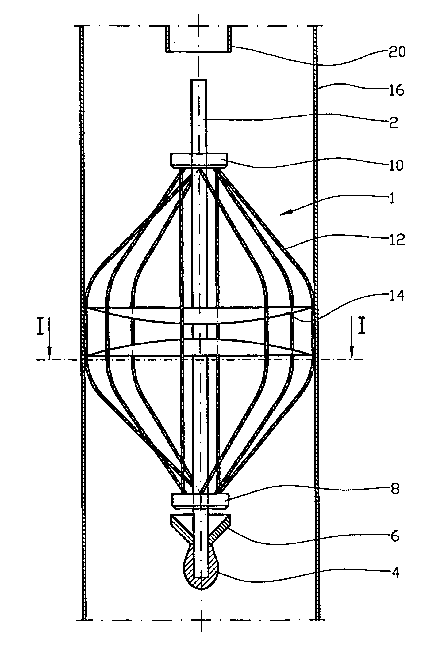
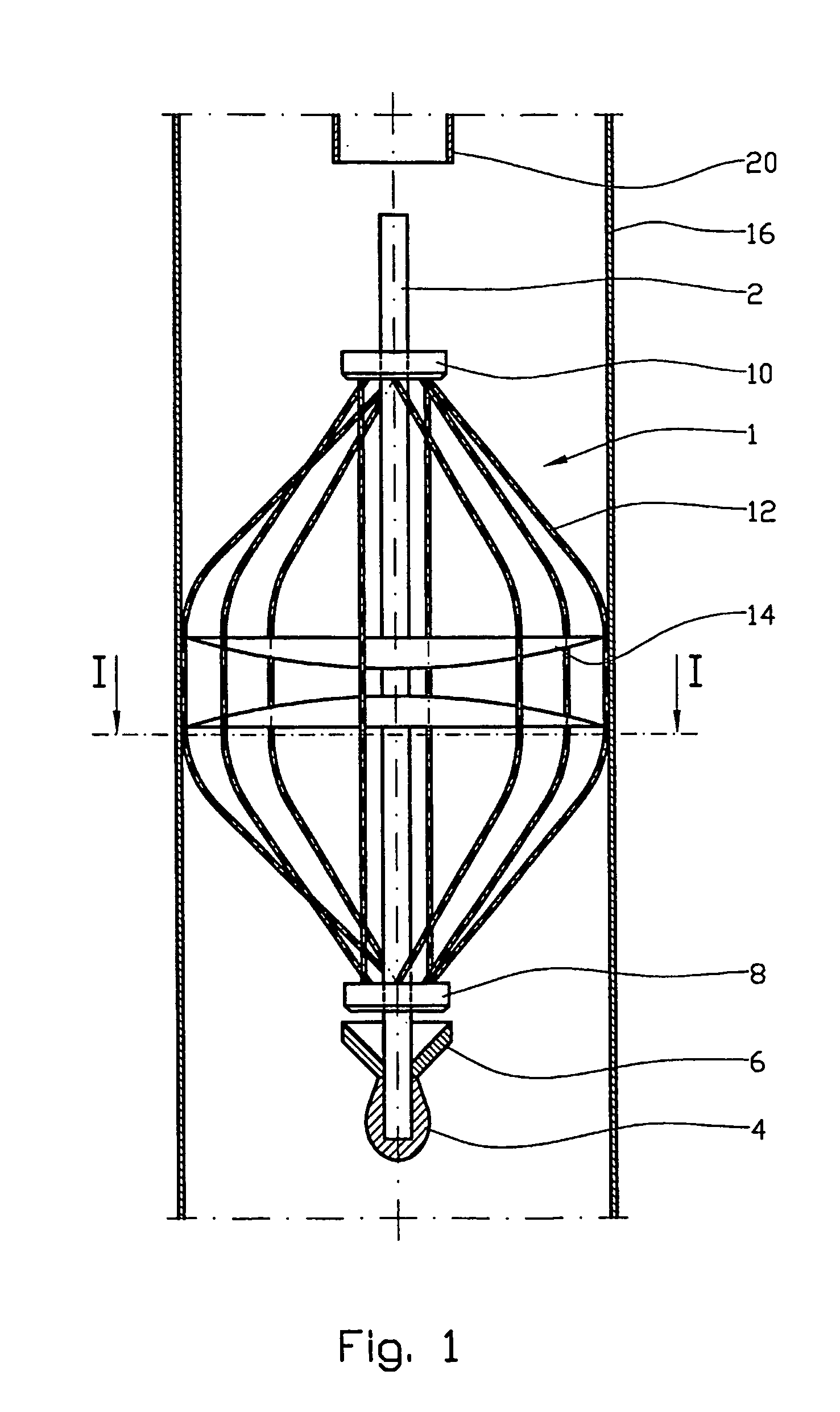
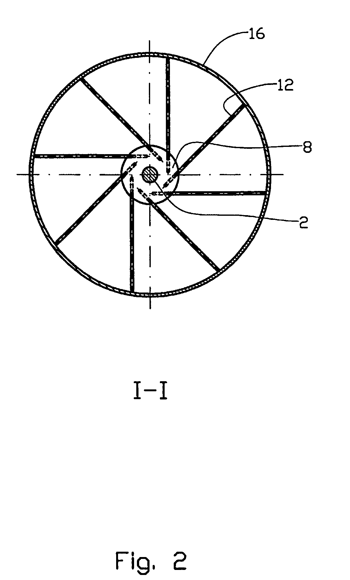
[0019]In the drawings, see FIGS. 1 and 2, reference number 1 denotes a diaphragm bow comprising a central rodlike mandrel 2, the lower end portion of which is rigidly mounted to a guiding body and at least one packing 6, a boss 8 rigidly mounted to the mandrel 2, and a boss 10 that may travel along the mandrel 2.

[0020]A number of bow slats 12 are fixed between bosses 8 and 10, preferably distributed in an even manner about the longitudinal axis of the mandrel 2. The respective end portions of the bow slats 12 are rigidly mounted to the bosses 8 and 10 in a manner such as to assume an outward bow relative to the body when in the neutral position. As an example, the bow slats 12 may be glued in bores 18 in the bosses 8 and 10. The direction of the bores 18 relative to the longitudinal axis of the rod 2 and the radial direction of the bosses 8 and 10 is adjusted according to the diameters the diaphragm bow 1 is to assume in the transport state and in the operative state.

[0021]One or mo...


PUM


Abstract

A device for keeping liquids separate in a pipe, especially for use in a petroleum well, where the device comprises a diaphragm, which in its operative position and through use of pretensioned slats is stretched across the cross section of the pipe, and where each of the two end portions of the slats is connected to a boss, respectively, in a manner such that each the slats forms an outward bow relative to the common axis of the bosses, when in the neutral position.

Description

RELATED APPLICATION[0001]This application is the U.S. National Phase of PCT / NO02 / 00124 filed Mar. 25, 2002 and claims priority to Norwegian Patent Application No. 20011529 filed Mar. 26, 2001 and to Norwegian Patent Application No. 20012867 filed Jun. 11, 2001, which are hereby incorporated by reference herein.BACKGROUND OF THE INVENTION[0002]1. Field of the Invention[0003]This invention regards a device, hereinafter termed a diaphragm bow, designed to segregate or separate liquids in a pipe, as is normally done during cementation work in a petroleum well, where use is often made of liquids having different density, and where mixing of the liquids would cause the cementation to be totally or partially unsuccessful.[0004]2. Description of Related Art.[0005]A petroleum well in which a casting operation is to be carried out will ordinarily contain drill fluid. When the grouting compound, which is slightly more viscous and has a higher density than drill fluid, is introduced at the desi...

Claims


Application Information

Patent Timeline
IPC IPC(8): E21B33/13E21B33/136E21B33/14
CPCE21B33/136
Inventor ANG.REBRAT, PER ARILD
Owner DA PERIGON
Why Eureka
Try Eureka