Rattle for attracting fish

a technology for attracting fish and rattles, which is applied in fishing, other angling devices, animal husbandry, etc., can solve the problems of affecting the effect of fishing line movemen

Inactive Publication Date: 2008-01-03
PIXTON DENNIS N
View PDF7 Cites 2 Cited by
  • Summary
  • Abstract
  • Description
  • Claims
  • Application Information

AI Technical Summary

Benefits of technology

[0014] The present invention, in one embodiment comprises a unique rattle that is attachable to a fishing weight, which is sometimes called a sinker, or that is used with a fishing weight, or that is used with an artificial soft or hard fishing lure. The improved and unique rattle includes a hollow cylindrical member capped on both ends with a thin membrane with an annular member located within the hollow cylindrical member. The length of the hollow member in conjunction with the outer diameter of the annular member causes the annular member to strike one side and then the other side end producing a plurality of clicking sounds with slight movement of the fishing line. The slight movement of the rattle causes the annular member to pivot within the hollow cylindrical member and strike either of the cap ends, thereby emitting the clicking sounds. In another embodiment, a small diameter sleeve extends axially within the center of the hollow cylindrical member. In this embodiment, the annular member includes an internal diameter that is sufficiently large such that the sleeve does not interfere with the pivoting action within the hollow cylindrical member.

Problems solved by technology

There are disadvantages to the generous movement required to generate the clicking sound.
Depending upon the location of the annular member within the air chamber and lateral movement of the sinker, it is possible that the annular may pivot and strike one inner wall; however, in general and under most conditions the annular will generate a noise by sliding within the air chamber rather than pivoting.
In prototype testing, it has been determined that the prior art rattles above noted are generally ineffective in performing their intended purpose.
Either the noise produced is to too low or soft to be effectively heard outside the rattle, or the noise produced is intermittent, or the rattle is insufficiently sensitive to generate noise with slight motions of the fishing line.

Method used


Image

  • Rattle for attracting fish
  • Rattle for attracting fish

Examples


Embodiment Construction

[0020] As required, detailed embodiments of the present invention are disclosed herein; however, it is to be understood that the disclosed embodiments are merely exemplary of the invention, which may be embodied in various forms. Therefore, specific structural and functioning details disclosed herein are not to be interpreted as limiting, but merely as a basis for the claims and as a representative basis for teaching one skilled in the art to variously employ the present invention in virtually any appropriately detailed structure. Additionally, the verbiage used herein is intended to better enable a person to understand the invention and therefore, such verbiage is not to be interpreted as limiting the invention.

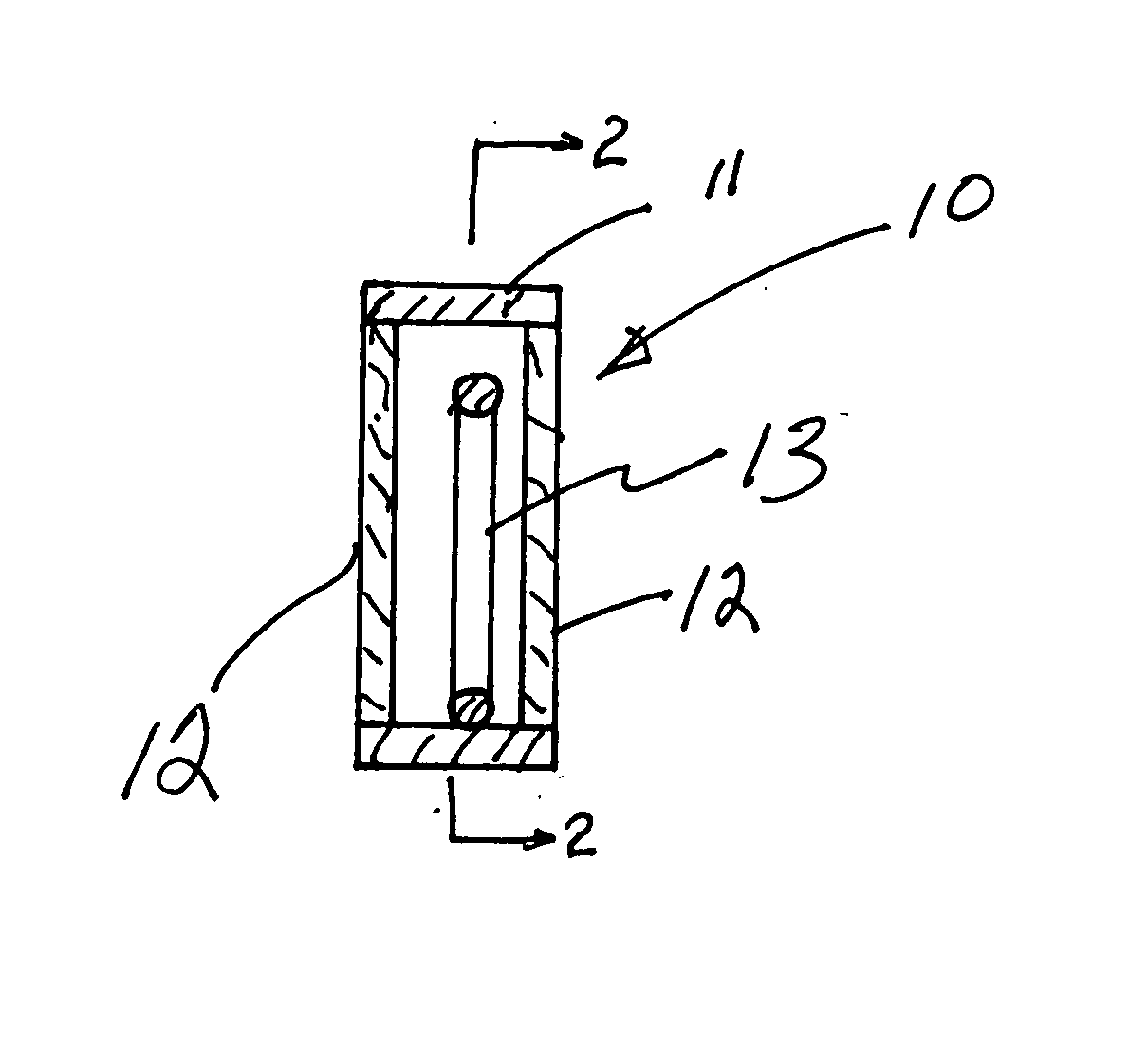
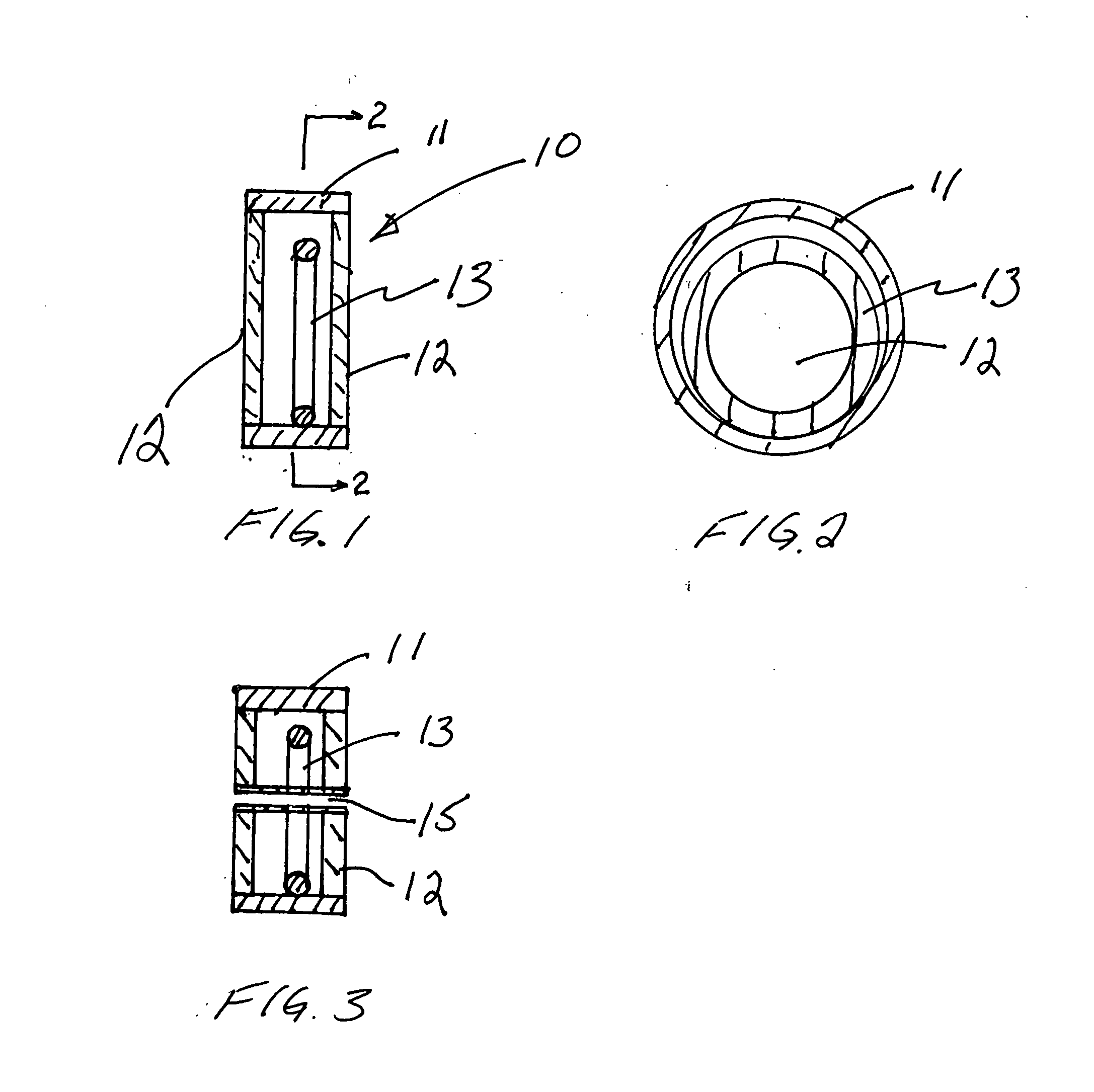
[0021] The details of the improved rattle 10 are shown in FIGS. 1 and 2. In this embodiment an annular body member 11 which comprises a hollow, substantially cylindrical member, or its equivalent, is fitted with end caps 12. An annular or ring like member 13 is located with...


PUM


Abstract

An improved rattle for attracting fish includes a hollow cylindrical chamber that is sealingly closed by ultra thin end caps. An annular, ring like member is positioned within the closed chamber so as to rest on its edge on the inner diameter of the closed chamber. The chamber diameter is larger than the outer diameter of the annular member thereby allowing the annular member to pivot on its edge when the rattle is rocked back and forth along its axial axis. The length of the chamber is relatively short. The pivoting causes the annular member to strike the sides of the closed chamber thereby producing a type of clicking sound that is known to attract fish. The combination of the ultra thin end caps and short chamber provides for improved loudness and sensitivity to slight motions of the rattle.

Description

CROSS REFERENCE TO RELATED APPLICATIONS [0001] This application is related to U.S. Provisional Application Ser. No. 60 / 561,494, filed on Apr. 13, 2004, and is a continuation in part of application Ser. No. 11 / 105,247, filed Apr. 13, 2005, entitled Rattle For Attracting Fish.BACKGROUND OF THE INVENTION [0002] 1. Field of the Invention [0003] This invention relates in general to the field of fishing rattles and in particular to rattle to attract fish which rattle can be used alone or in combination with a fishing lure. [0004] 2. Description of the Prior Art [0005] Fishermen using a pole and fishing line have for many years sought ways to better their chances of catching fish. It is known that fish have a lateral line on their body that responds to sound. Accordingly, devices have been advanced in the prior art to use the sound responding lateral line to attract fish and help catch them. These prior art devices have involved myriad technologies including electronic generation of variou...

Claims


Application Information

Patent Timeline
Patent Type & Authority Applications(United States)
IPC IPC(8): A01K85/01
CPCA01K97/02A01K85/01
Inventor PIXTON, DENNIS N.
Owner PIXTON DENNIS N
Why Eureka
Try Eureka