Multi-tube bundling type vortex tube cold and hot separator device

A cold and hot separation, vortex tube technology, applied in the direction of refrigerators, refrigeration and liquefaction, machine operation, etc., can solve the problem that the cooling capacity is difficult to meet the use requirements, the cooling capacity of a single vortex tube is small, and the separation of cold and heat is not very good and other problems, to achieve the effect of improving cooling and heating efficiency, ensuring the matching accuracy, and simple and feasible structure.

Active Publication Date: 2014-08-13
DALIAN UNIV OF TECH
View PDF9 Cites 0 Cited by
  • Summary
  • Abstract
  • Description
  • Claims
  • Application Information

AI Technical Summary

Problems solved by technology

[0003]Traditional single-acting vortex tubes generally have the advantages of single and simple structure, no moving parts, convenient operation, safe and reliable operation, low cost, and easy maintenance. It has the functions of refrigeration and heating. In the past, people's research on vortex tubes almost all focused on the characteristics of this type of single-tube vortex tube. They are all patents for single-tube vortex tubes with different structures. Although single-tube vortex tube refrigerators are suitable for certain occasions, they have no rotating parts because of their special structure, and the devices are generally small, so they can be used in places with small spaces.
However, it is precisely because the volume and capacity of the device itself is too small that the cooling capacity is very small.
When there is a large demand for capacity, its cooling capacity is obviously difficult to meet the use requirements
The cooling capacity of a single vortex tube is too small, which is their common defect, which greatly limits its application range.
Because a set of devices actually only includes one vortex tube, and because some vortex tubes are limited by structural size, etc., the effect of cold and heat separation is not very good, and the cooling efficiency is low.
And because the whole device is small in size, no matter how enlarged it is, it is difficult to achieve a large cooling capacity.

Method used


Image

  • Multi-tube bundling type vortex tube cold and hot separator device
  • Multi-tube bundling type vortex tube cold and hot separator device
  • Multi-tube bundling type vortex tube cold and hot separator device

Examples


Embodiment Construction

[0034] Below in conjunction with accompanying drawing and specific embodiment the present invention will be further described:

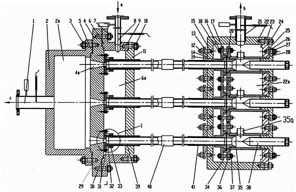
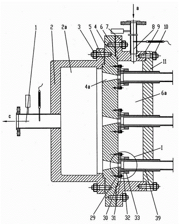
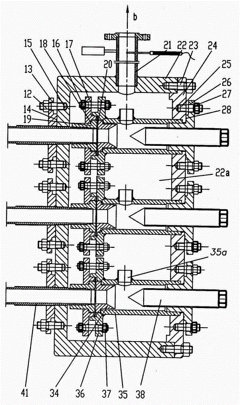
[0035] figure 1 , 2 , 3 shows the structure of a multi-tube bundled vortex tube cold and hot separation device. In the figure, a multi-tube bundled vortex tube cooling and heat separation device includes multiple single-tube vortex tube refrigerators, and it also includes a cold air collection chamber 2 , an air inlet chamber 6 and a hot end collection chamber 22 . The intake cavity 6 is fixedly connected with the diffuser plate 4 and the intake cavity cover 11 to form an intake cavity 6a, and the cold air collection cavity 2 is fixedly connected with the diffuser plate 4 to form a cold air collection cavity 2a. The hot end collection cavity 22 is fixedly connected with the hot end cover 24 to form a hot end collection cavity 22a.

[0036]The vortex tube cold and heat separation device adopts a multi-tube cluster structure. 2-50 vortex tube refri...


PUM


Abstract

The utility model relates to a multi-tube bundle type vortex tube cold and hot separation device, which belongs to the application technical field of pressure gas throttling and pressure reduction, gas refrigeration and high and low temperature separation. The device constructs an integral air intake chamber, a cold air collection chamber and a hot end collection chamber that contain multiple vortex tubes and are independently closed, and can realize the whole process of simultaneous and continuous air intake and the separation of hot and cold air. Because the device expands the space capacity of the entire chamber, the contradiction between meeting the basic applicable conditions of the vortex tube and the large flow processing requirements in the entire large device is resolved. It is suitable for occasions that require a large amount of processing, so that it can meet the requirements of greatly doubling the cooling capacity and heating capacity. The device can be used in large-scale industrial production occasions, and is a device that integrates cooling and heating, and can realize the separation of cold and heat. It is suitable for refrigeration and heating of various gases, and has the advantages of combined, integrated, skid-mounted and detachable.

Description

technical field [0001] The invention relates to a multi-tube bundle type vortex tube cold and hot separation device, which belongs to the technical field of pressure gas throttling and pressure reduction, gas refrigeration and high and low temperature separation applications. Background technique [0002] Vortex tube technology is a technology with a relatively long history of development. It generally directly uses the pressure energy of the gas to finally separate the gas into two parts, cold and hot. When working, the pressure gas enters the annular gas storage and buffer chamber outside the vortex chamber along the inlet port. Under the action of the pressure difference between the inlet and outlet, it passes through a single or multiple nozzles and is injected into the vortex chamber at a high speed tangentially along the pipe wall. Strong swirling motion is generated in the vortex chamber, which induces the vortex effect. After vortex transformation, it is separated in...

Claims


Application Information

Patent Timeline
Patent Type & Authority Patents(China)
IPC IPC(8): F25B29/00F25B9/04
Inventor 朱彻胡大鹏代玉强邹久鹏刘培启王泽武张礼鸣张大为
Owner DALIAN UNIV OF TECH
Why Eureka
Try Eureka