
Interlocking between ROM and racking feeder mechanism for drawout module

a technology of feeder mechanism and drawout module, which is applied in the direction of electrical equipment, switchgear, substation/switching arrangement details, etc., can solve the problems of door-independent handle mechanism arrangement and chance of acciden

Pending Publication Date: 2022-03-03
SCHNEIDER ELECTRIC INDIA
View PDF2 Cites 0 Cited by
  • Summary
  • Abstract
  • Description
  • Claims
  • Application Information

AI Technical Summary

Benefits of technology

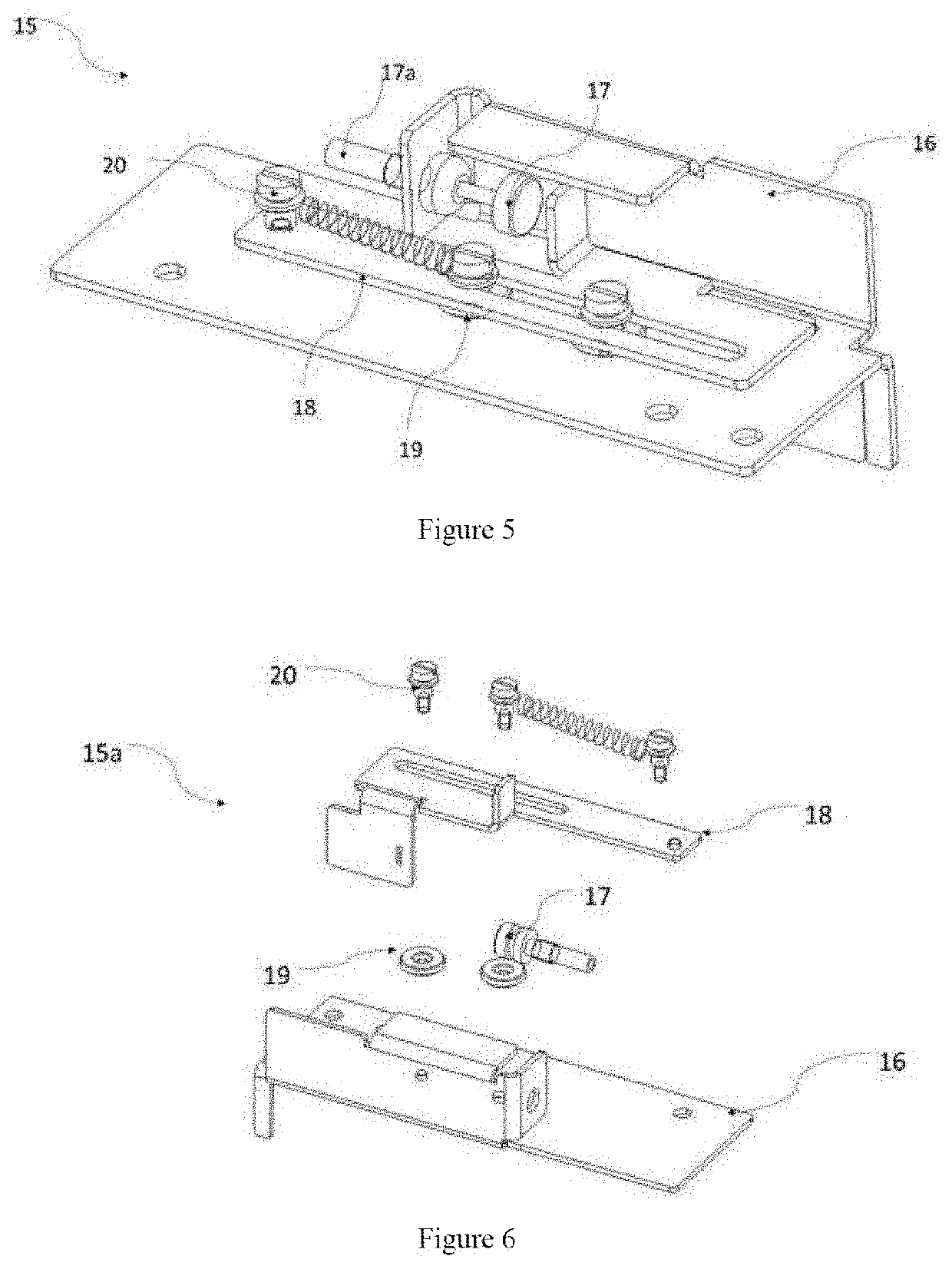
The present invention is aimed at preventing unauthorized access to a withdraw-able type MCCB in a switch ON and panel door open condition. This is achieved through an interlock slider that has a slot to block and unblock access to the racking screw. The interlock slider is also equipped with two step screws and a spring to maintain its position in the locked condition and restrict user access to the racking screw. This makes the MCCB safer and more secure from tampering or unauthorized access.

Problems solved by technology

However, in current scenario, there is no such arrangement for Door independent handle mechanism's.
There is a chance of accident when user opens the door in ON condition by using defeat tool and get access to insert the rod on racking screw.

Method used


Image

  • Interlocking between ROM and racking feeder mechanism for drawout module
  • Interlocking between ROM and racking feeder mechanism for drawout module
  • Interlocking between ROM and racking feeder mechanism for drawout module

Examples


Embodiment Construction

presented later.

[0012]The object of present invention is to overcome the problems of prior arts.

[0013]The Primary object of the present invention is to prevent the access of racking screw in withdraw-able type MCCB in switch ON and panel door open condition.

[0014]Another object of invention is to provide an interlock which ensures, operating handle is directly mechanically connected to the unit irrespective of door position.

[0015]One aspect of present invention is to provide an interlocking arrangement for Switching Devices for blocking the switching device in ON condition, comprising a feeder assembly with Interlock comprising of a feeder assembly and a Racking screw interlock assembly, wherein the feeder assembly comprises a Switching device adapted to be connected to a Feeder base plate of the feeder assembly and mechanically connected with an interlock slider (18) by means of a locking clutch cable; and a feeder channel upon which the Racking screw interlock assembly is fixedly ...


PUM


Abstract

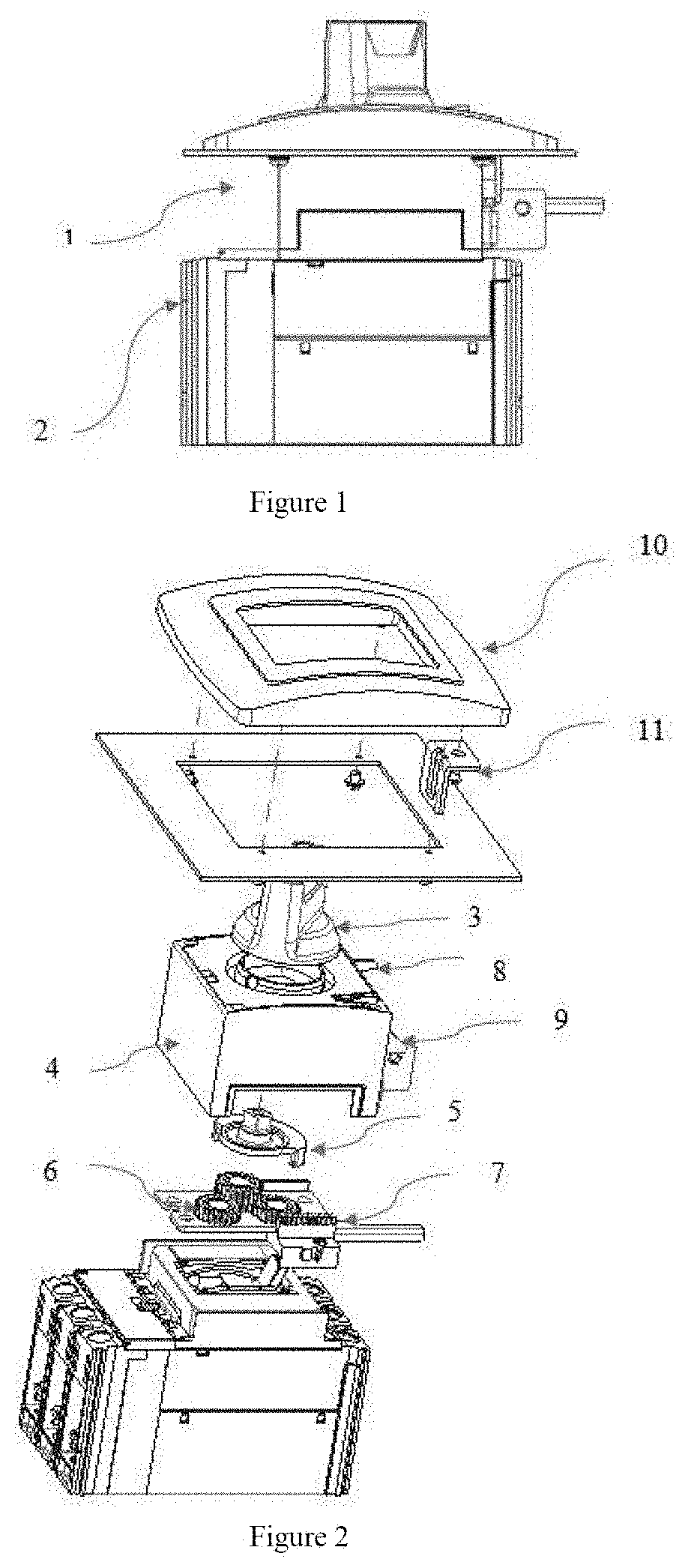
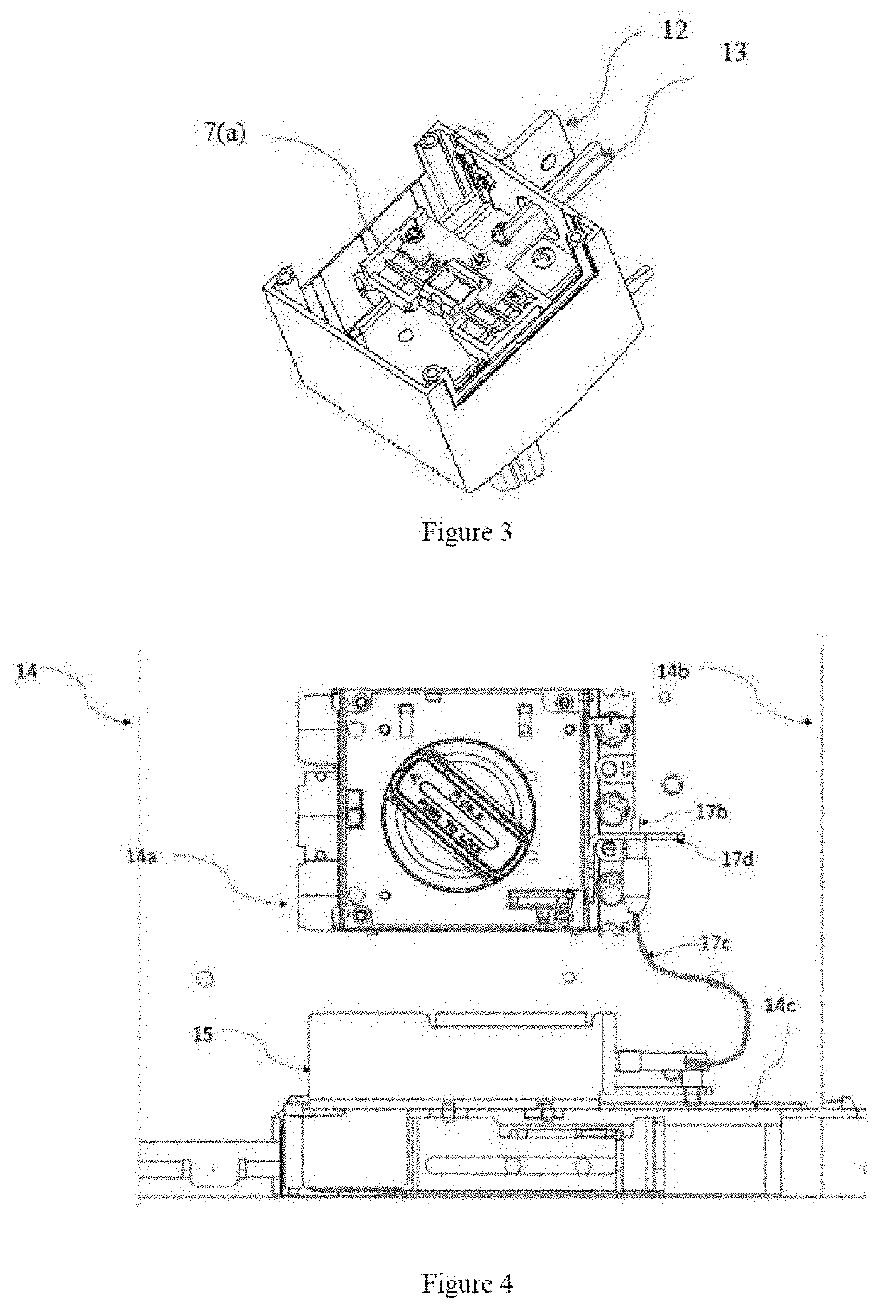
The invention generally relates to an arrangement / integration, particularly for Switching Devices with external feeder, more particularly relates to a separate package of interlock system to be used for withdraw able type MCCBs with Direct operating handle to prevent unintentional racking operation of feeder. An interlocking arrangement for Switching Devices for blocking the operation of the switching device when feeder door is open, comprising a feeder assembly with Interlock (14) comprising of a feeder assembly and a Racking screw interlock assembly (15), wherein the feeder assembly comprises a Switching device (2, 14a) adapted to be mounted on a Feeder base plate (14b) of the feeder assembly and mechanically connected with an interlock slider (18) by means of a locking clutch cable (17); and a feeder channel (14c) upon which the Racking screw interlock assembly (15) is fixedly mounted by means of an interlock base plate (16) which is adapted to be mechanically connected to the feeder channel by means of plurality of fixing holes; and wherein the racking screw interlock assembly (15) comprises of the interlock base plate (16) adapted to accommodate the locking clutch cable (17) and the interlock slider (18) slidably mounted on the baseplate by means of combine function of plurality of step screws (20) and slots (16e) provided on the base plate; wherein two step screws are fixedly positioned on the interlock base plate (16c) by means of slots (16e) and operably connected by a spring mechanism and the other step screw is positioned on the interlock slider (18a) to provide slight movement of slider (18); wherein Locking clutch cable (17) and slider (18) is assembled in such a way that user cannot access the racking screw (14d) of the feeder (21) when locking clutch cable (17) is locked by the switching device.

Description

[0001]This application claims the benefit of Serial No. 202021037153, filed 28 Aug. 2020 in India, and which application is incorporated herein by reference. To the extent appropriate, a claim of priority is made to the above disclosed application.TECHNICAL FIELD OF THE INVENTION[0002]The invention generally relates to an arrangement / integration, particularly for Switching Devices with external feeder. The present invention more particularly relates to a separate package of interlock system between direct operating handle with MCCB and external feeder to prevent unintentional racking operation in withdrawable type MCCB.BACKGROUND OF THE INVENTION[0003]The use of switching devices, conventionally known as Switchgear, is well known for making, breaking, regulating and to provide safety in a typical electrical distribution system. These devices are generally mounted inside a panel door for added safety of operator. Most often these switching devices are operated either from outside or ...

Claims


Application Information

Patent Timeline
IPC IPC(8): H02B11/133H02B1/36
CPCH02B11/133H02B1/36
Inventor DASH, DEBASMITAVISHWAKARMA, SANJEET
Owner SCHNEIDER ELECTRIC INDIA
Learn More