

Modular case handle positioning device
a module-type, handle technology, applied in the direction of coupling device connection, electrical apparatus casing/cabinet/drawer, coupling parts engagement/disengagement, etc., can solve the problem of excessive vibration force between the modular case, extremely large vigorous force being needed to re-withdraw the modular case, and inconvenient to assemble and disassembl
- Summary
- Abstract
- Description
- Claims
- Application Information
AI Technical Summary
Benefits of technology
Problems solved by technology
Method used
Image

Examples
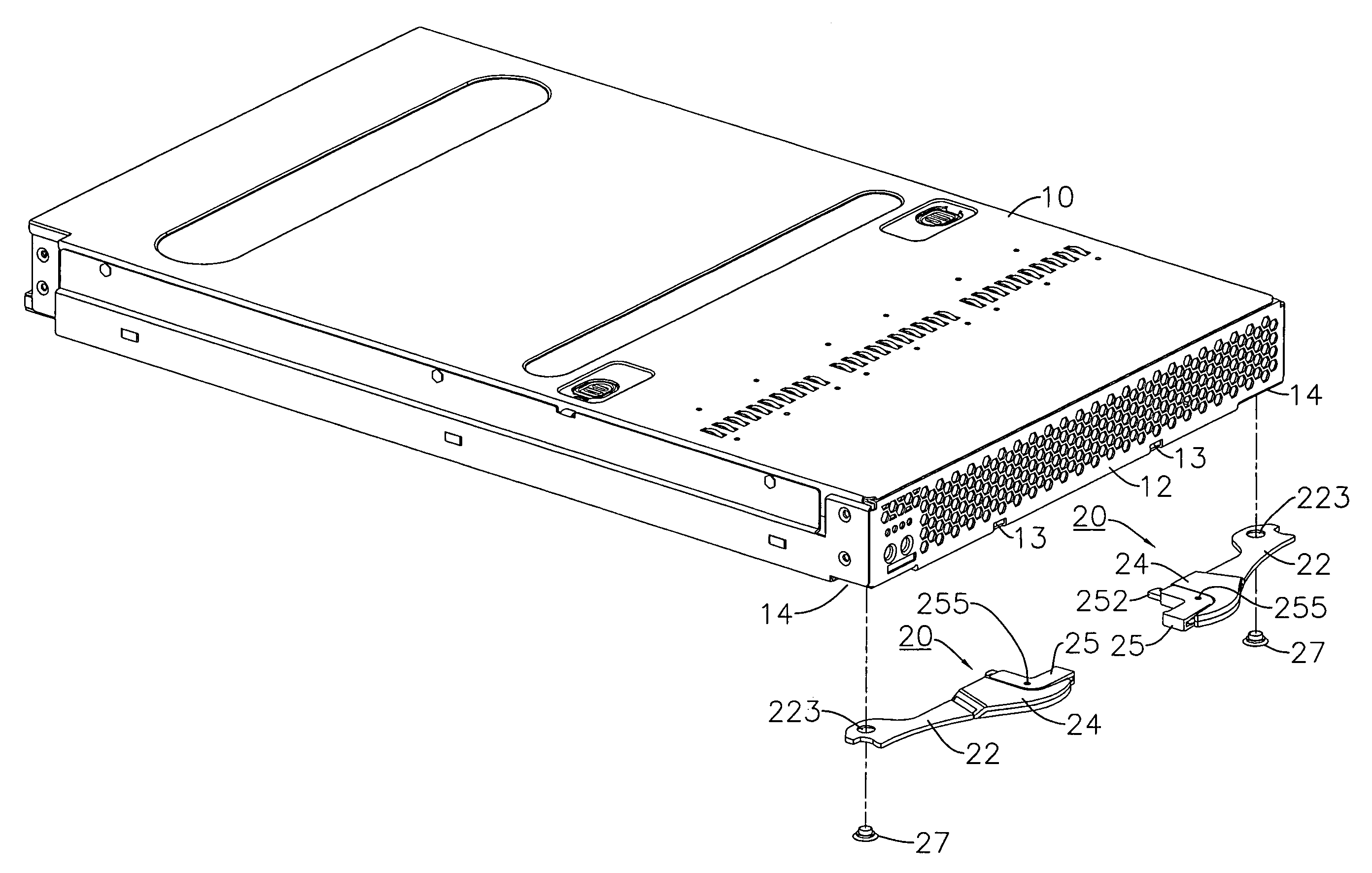
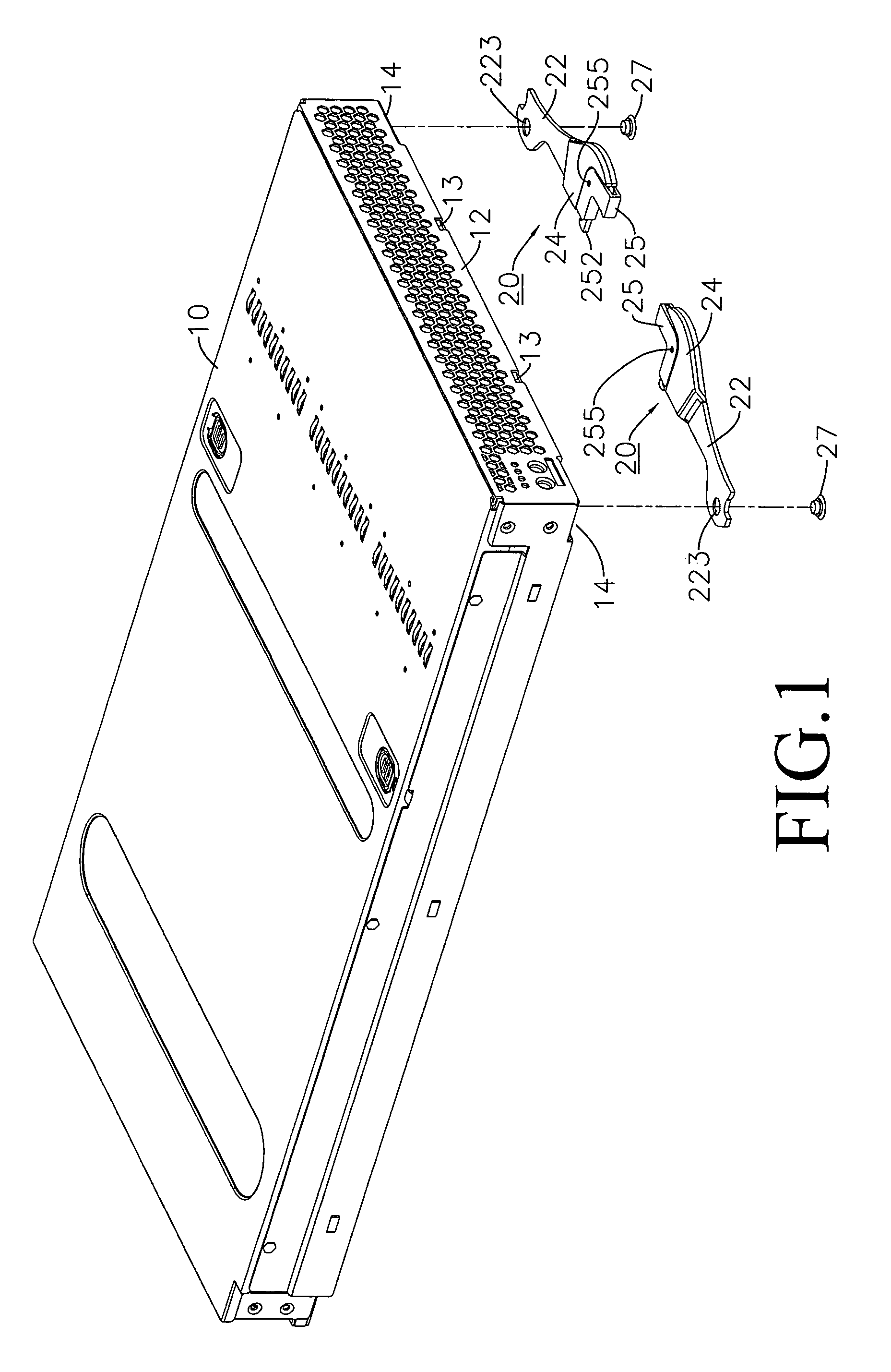
case 10
[0018]a rectangular modular case 10, wherein undersides of a front surface 12 is defined with depressed indentations 14, (14), each of which are provided with an inner groove surface 141, and an underside of the front face is defined with position fixing holes 13;
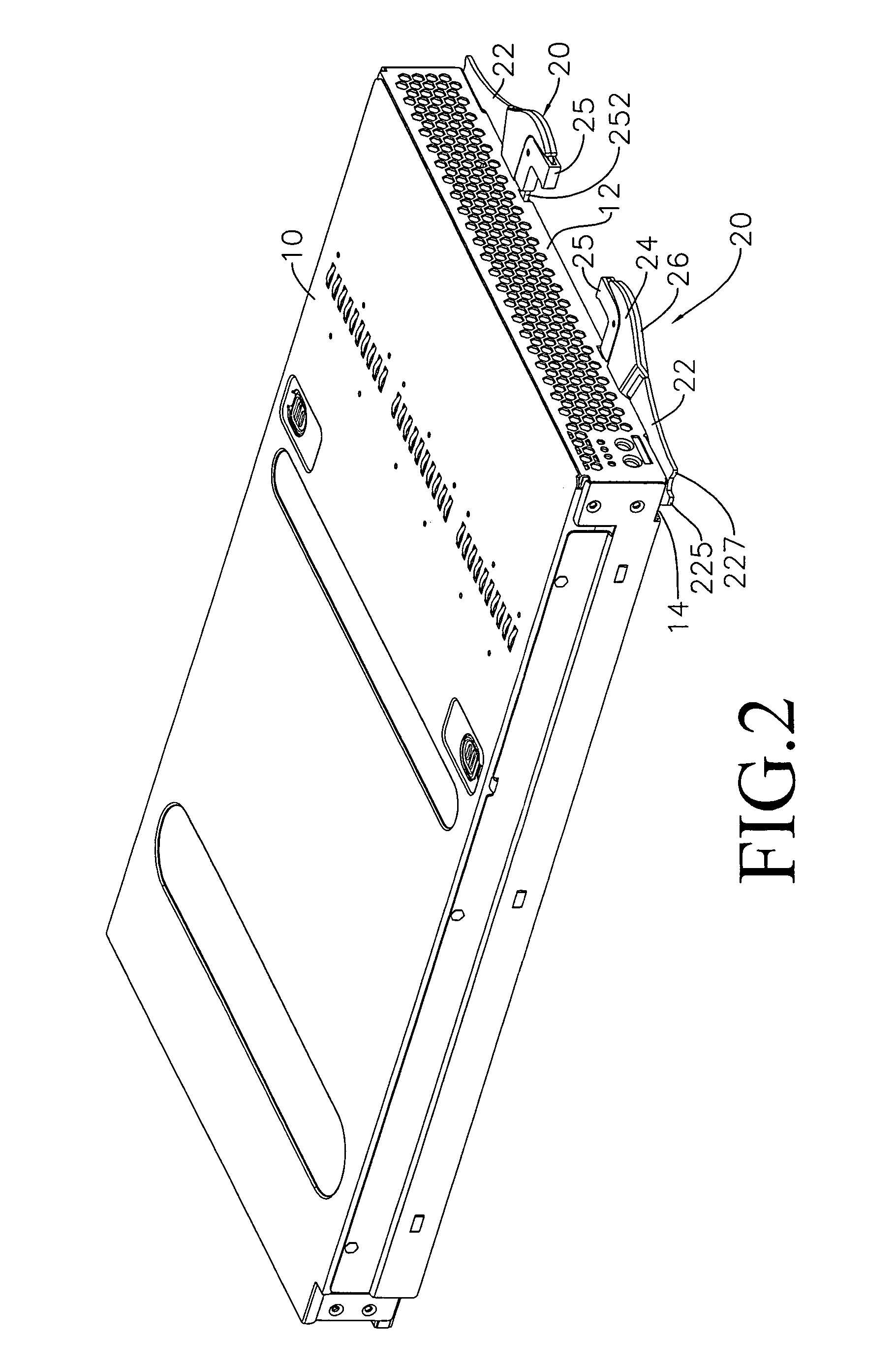
[0019]at least more than one handle 20, (20) is movable connected to a lower surface of two sides of the modular case 10, and each of the handles 20, (20) are structured to comprise:
[0020]a platelike main body 22 (see FIG. 3), wherein an upper cover 24 is affixed to an upper surface of a front plate 221, and a lower cover 26 is affixed to a lower surface, moreover, a front pivot joint hole 222 is defined in the front plate 221, and a rear pivot joint hole 223 is defined in a rear side of the main body 22; a side edge of the front plate 221 forms an L-shaped side 224;
[0021]an L-shaped linkage 25, a horizontal side of which forms a holding slot 251, a side end forms a hook 252, and a longitudinal through hole 253 is defined i...
PUM
 Abstract
Description
Claims
Application Information