
Utility iron golf club with weighting element

Inactive Publication Date: 2006-10-24
MIZUNO CORPORATION
View PDF11 Cites 61 Cited by
  • Summary
  • Abstract
  • Description
  • Claims
  • Application Information

AI Technical Summary

Benefits of technology

[0007]In an alternative embodiment this invention also utilizes different thickness in the face of a utility golf club iron to increase the initial velocity of the golf ball. The areas of varying thicknesses generate a spring-like or trampoline effect in the face of the golf club to increase the initial velocity of the golf ball. To maximize this trampoline effect, the face generally has three different thicknesses; the center of the face where the golf ball generally impacts is the thickest area, the top portion of the club is thinner than the center of the face, and the bottom portion is thicker than the top portion but thinner than the center of the face.
[0008]It is therefore an object of the present invention to provide an effective game improvement utility iron.

Problems solved by technology

Long irons, low lofted irons, often provide a challenge to some golfers because the low loft of the club causes the golf club head to be in a more upright position.
This upright position raises the center of gravity of the golf club head making it more difficult to elevate a golf shot because more weight of the golf club head is located above the center of gravity of the golf ball.
However, fairway woods are also usually longer and the design of the club head makes controlling the rotation of the club head more difficult.
Therefore, fairway woods are generally less accurate than long irons.
The smaller head helps lower the center of gravity; however, utility woods still retain the same characteristics that make them less accurate than long irons.
There are two deficiencies with the utility irons that are currently manufactured.
First, utility irons fail to utilize a face design in which the face of the golf club head has different thicknesses.
However, this design is inefficient because it reinforces areas unnecessarily, which both decreases the COR and prevents that weight from being distributed to either increase the moment of inertia or to lower the center of gravity.
The second deficiency of current utility irons is that the center of gravity of most utility irons is still too high for some golfers to effectively use these clubs.
Because it is necessary to maintain an effective swing weight of a golf club, it is impractical to simply attach a large weight across the entire sole of the golf club.

Method used


Image

  • Utility iron golf club with weighting element
  • Utility iron golf club with weighting element
  • Utility iron golf club with weighting element

Examples


Embodiment Construction

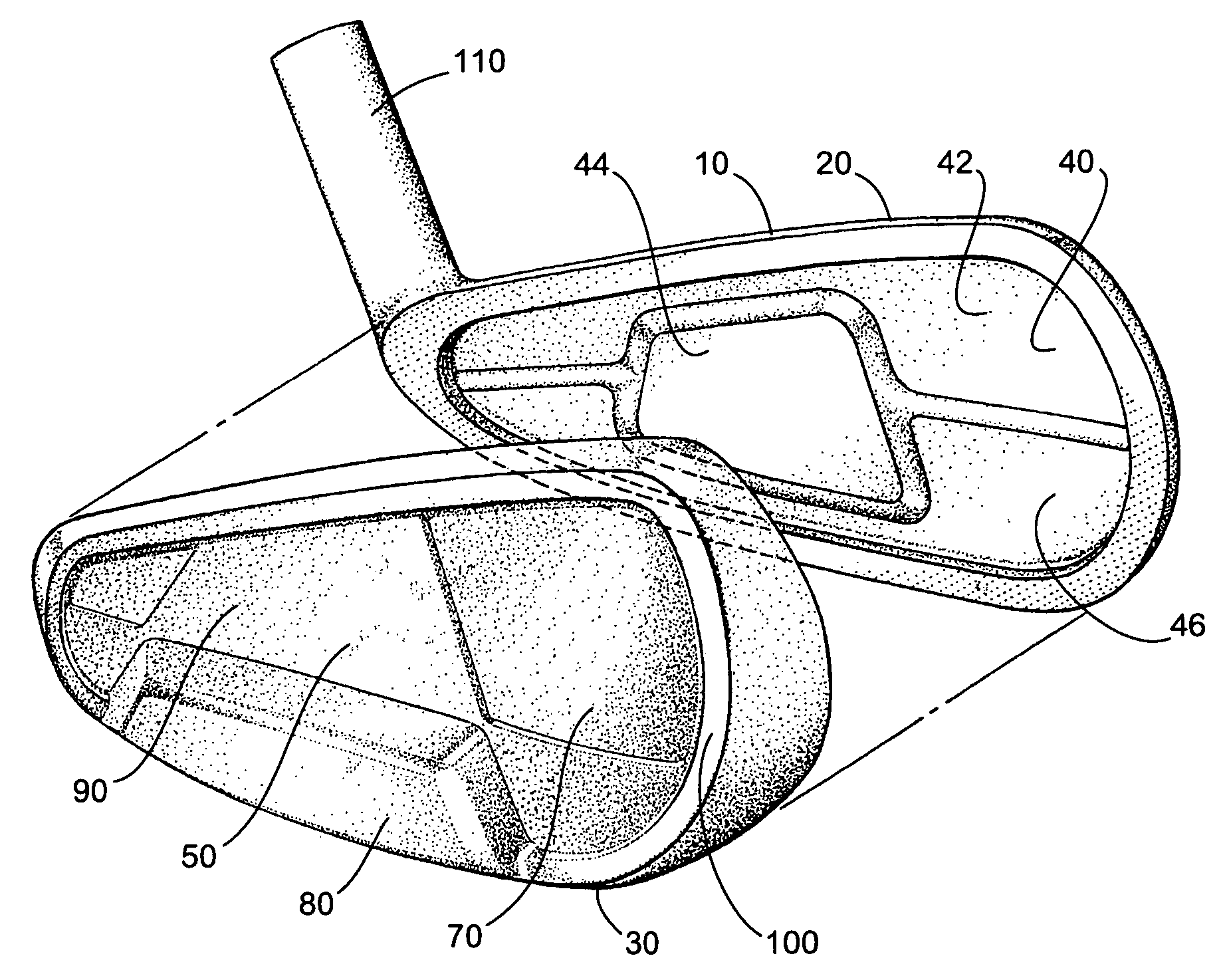
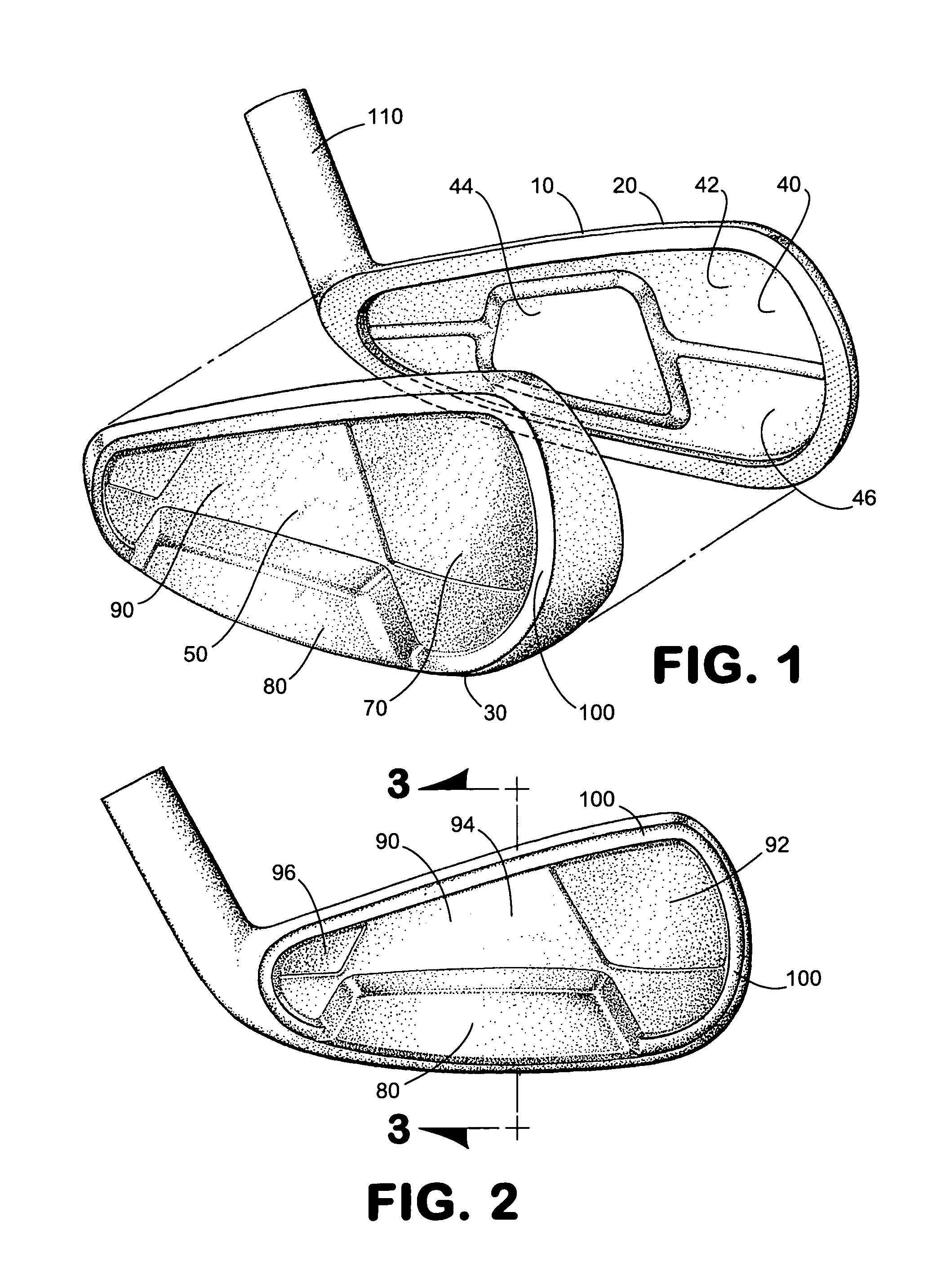
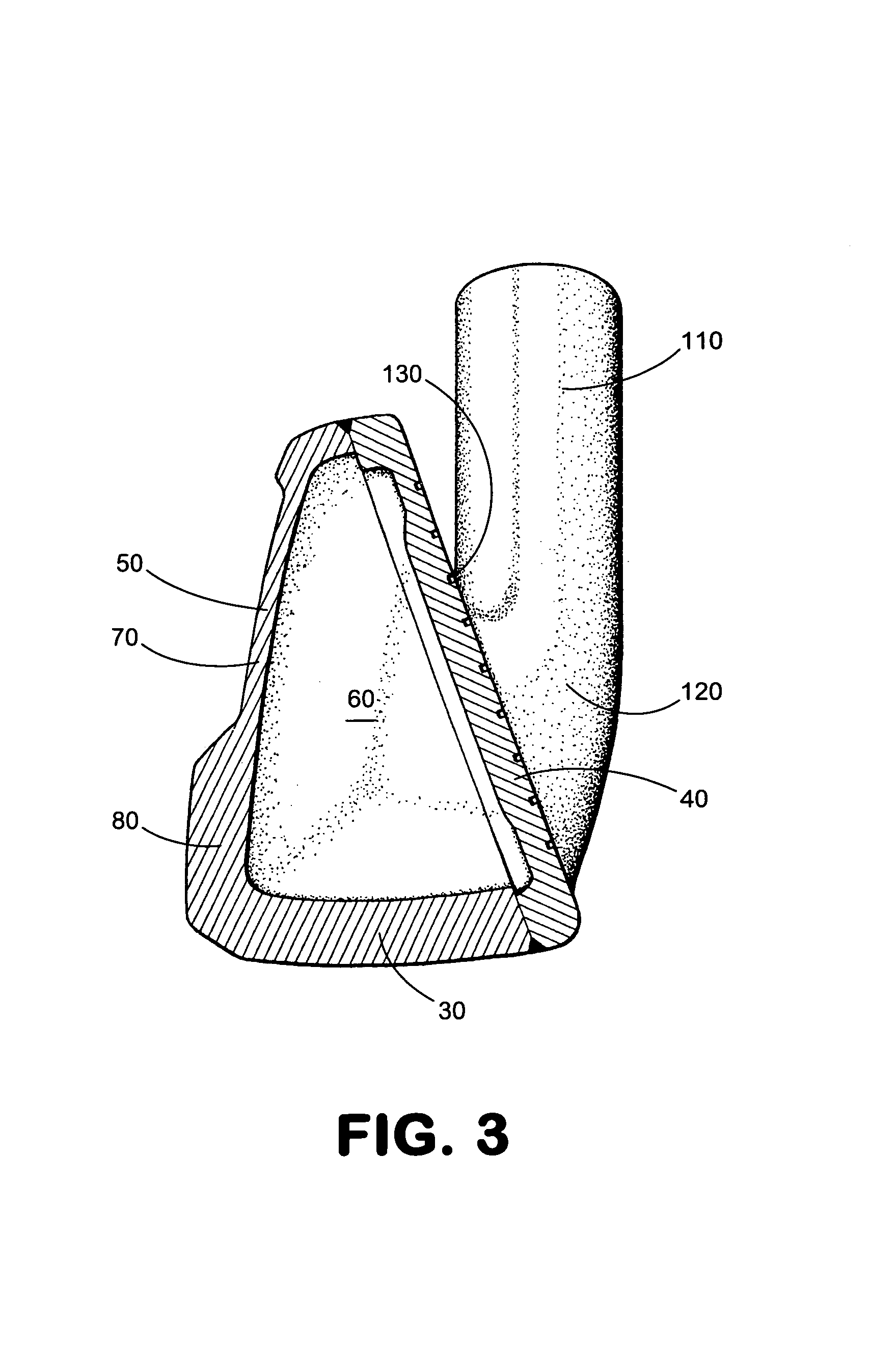
[0012]Referring now in more detail to the drawings, as can be seen in FIGS. 1,2, and 3, the golf club head 10 having a front plate 40 integral with a primary body 50 having a top 20, a sole 30, and a rear portion 90, forming a general periphery 70 wherein the primary body 50 and the front plate 40 define a hollow interior 60 and where the rear portion carries a weighting element 80 that protrudes behind the general periphery 70.

[0013]The weighting element 80 illustrated in FIG. 2 can be a trapezoid-like shaped bar that attaches to the rear portion 90 of the golf club head 10 and partially protrudes behind the general periphery 70 of the primary body 50. In addition, the rear portion 90 of the golf club head 10 in this embodiment is divided into three sections; the toe section 92, the middle section 94, and the heel section 96. The weighting element 80 is located on the middle section 94 to create a low, deep center of gravity, which generates a high launch angle.

[0014]The rear porti...


PUM


Abstract

A golf club head comprising of a front plate integral with a primary body having a top, a sole, a rear portion, and a general periphery wherein the primary body and the front plate define a hollow interior and where the rear portion carries a weighting element that protrudes behind the general periphery.

Description

BACKGROUND OF THE INVENTION[0001]This invention relates to a golf club head and more particularly to an improvement of a utility iron.[0002]Long irons, low lofted irons, often provide a challenge to some golfers because the low loft of the club causes the golf club head to be in a more upright position. This upright position raises the center of gravity of the golf club head making it more difficult to elevate a golf shot because more weight of the golf club head is located above the center of gravity of the golf ball. To address this problem, many high handicap golfers will chose to use fairway woods instead of long irons. Fairway woods generally have a lower center of gravity to make elevating the golf ball easier. However, fairway woods are also usually longer and the design of the club head makes controlling the rotation of the club head more difficult. Therefore, fairway woods are generally less accurate than long irons.[0003]To address the problems of both long irons and fairw...

Claims


Application Information

Patent Timeline
IPC IPC(8): A63B53/04
CPCA63B53/04A63B53/047A63B2053/0408A63B2053/0416A63B2053/0458A63B2053/0412A63B53/0412A63B53/0458A63B53/0408A63B53/0416A63B60/02A63B60/00
Inventor NAGAI, MASAOLLEWELLYN, DAVID G.
Owner MIZUNO CORPORATION
Learn More