Digital indoor antenna device

a digital indoor antenna and antenna technology, applied in the direction of indoor communication adaptation, non-resonant long antennas, antennas, etc., can solve the problem of not being able to receive the largest intensity of these signals (about 30% loss), and achieve the effect of reducing interference other polarized signals

Inactive Publication Date: 2006-10-24
TRANS ELECTRIC
View PDF6 Cites 64 Cited by
  • Summary
  • Abstract
  • Description
  • Claims
  • Application Information

AI Technical Summary

Benefits of technology

[0008]The main objective of the present invention is to provide a digital indoor antenna device to rec...

Problems solved by technology

The circular antenna can receive vertically and horizontally polarized signals, but cannot receive the largest inte...

Method used


Image

  • Digital indoor antenna device
  • Digital indoor antenna device
  • Digital indoor antenna device

Examples


Embodiment Construction

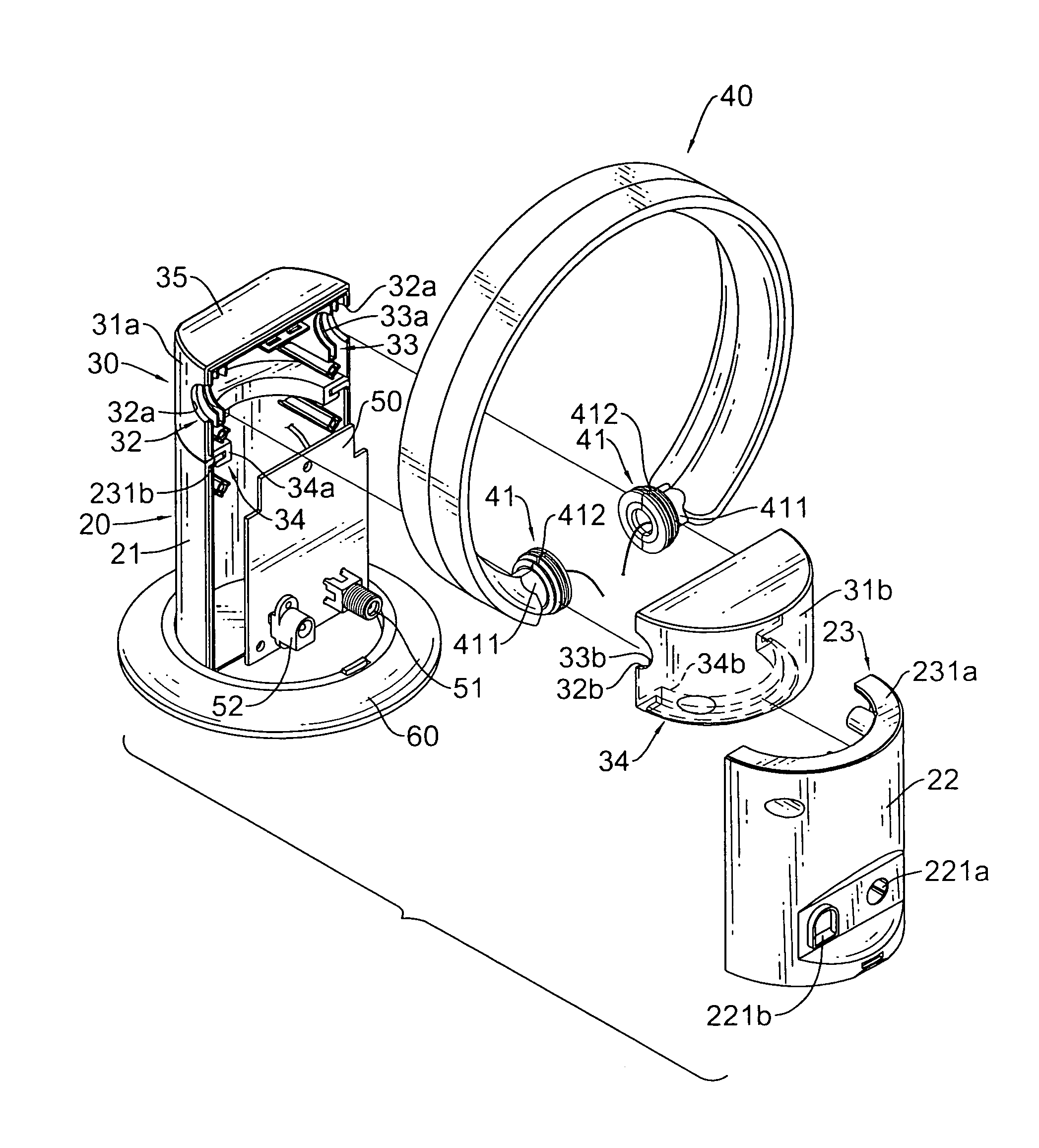
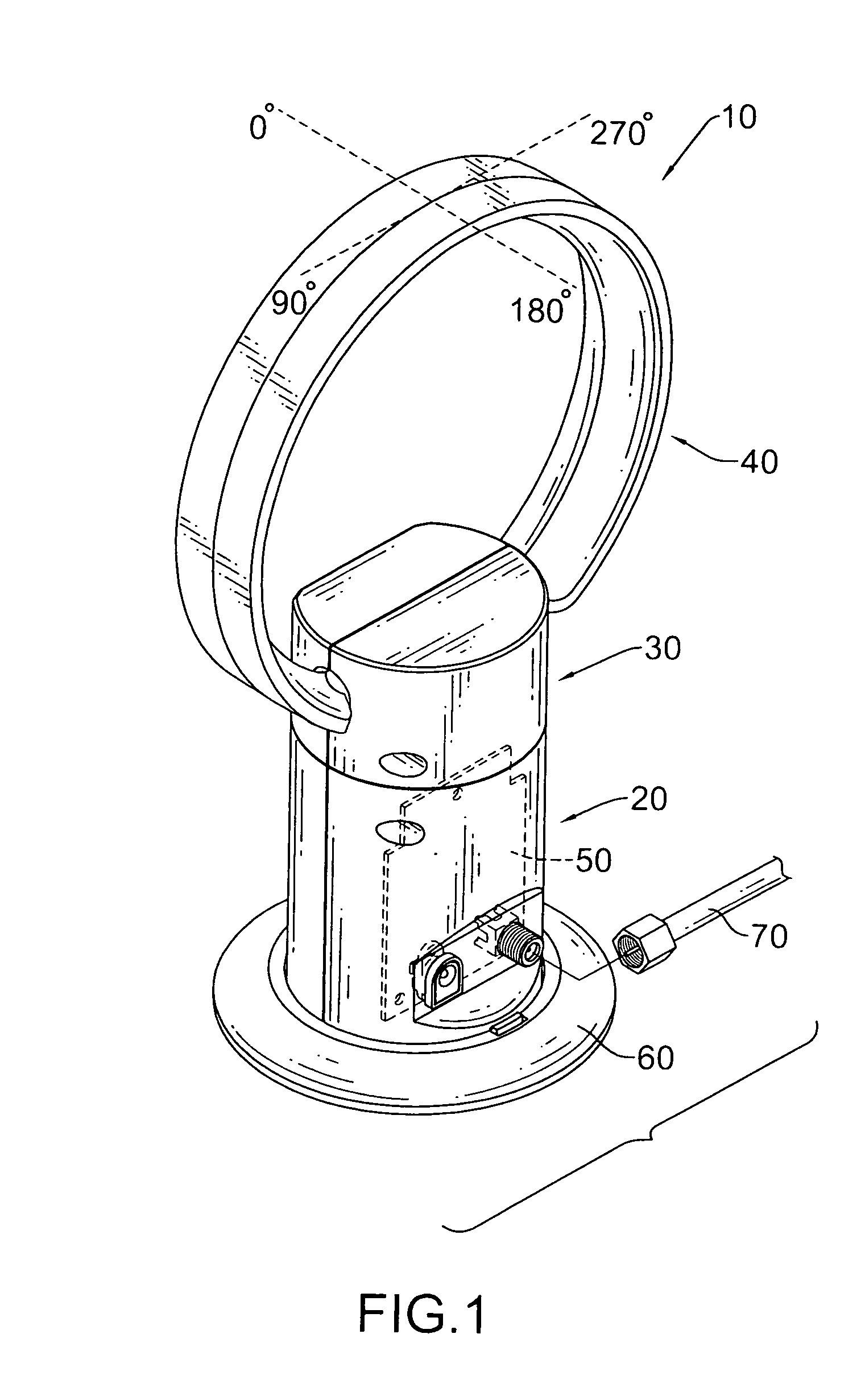
[0017]With reference to FIG. 1, a digital indoor antenna device (10) in accordance with the present invention has a casing (20), a pivotal seat (30), a circular antenna (40), a PCB (50) and an optional base (60). With further reference to FIG. 4, the pivotal seat (30) is connected to the casing (20), and the circular antenna (40) pivotally is connected to the pivotal seat (30), so the circular antenna (40) is mounted pivotally on the casing (20).

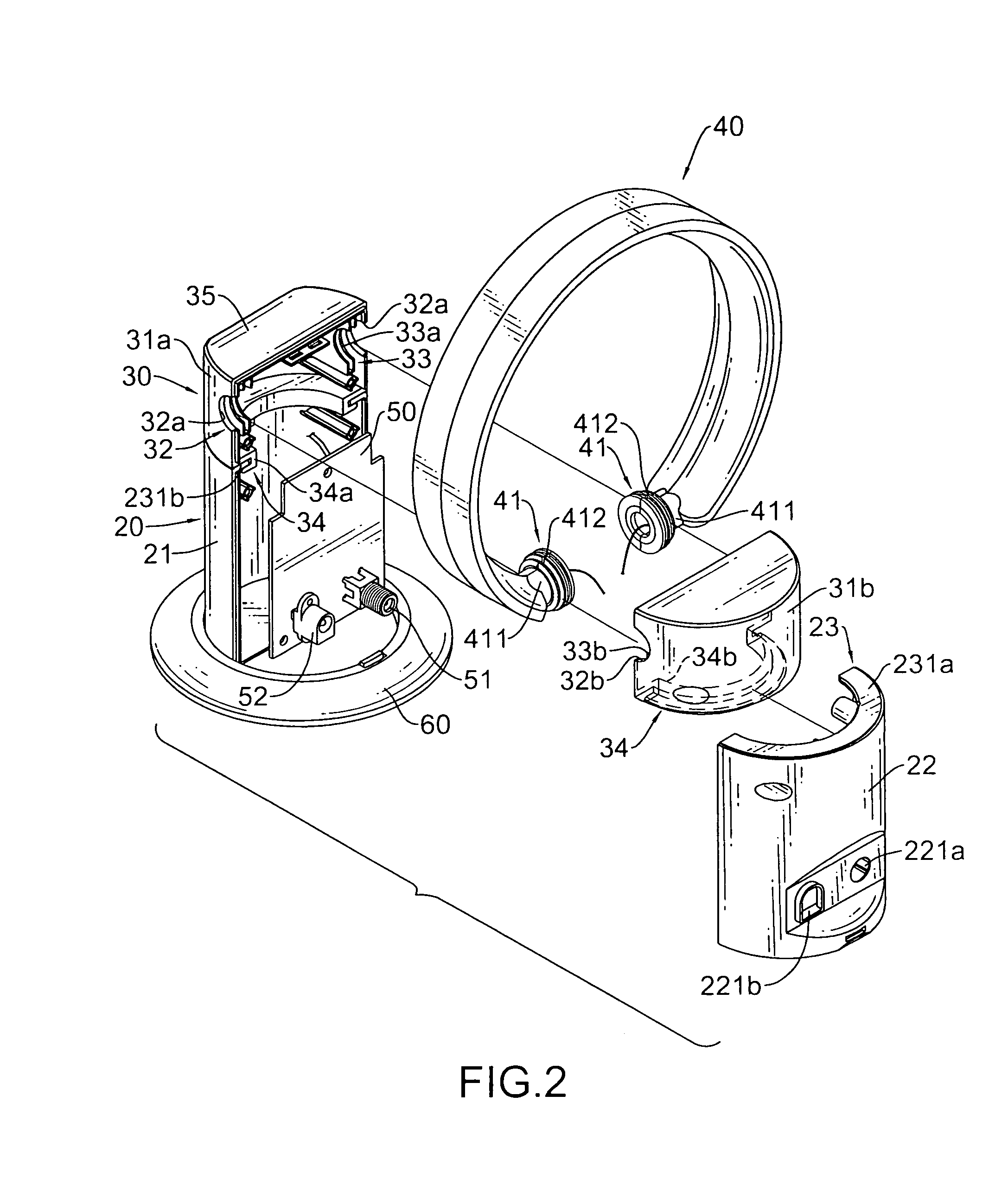
[0018]With further reference to FIG. 2, the casing (20) has a top and a bottom and can have a front cover (21), a rear cover (22) and an optional track (23). The rear cover (22) is attached to the front cover (21) to define an interior cavity and has two through holes (221a, 221b). The track (23) is formed at and extends in from the top of the casing (20) and may comprise two semicircular tracks (231a, 231b). The semicircular tracks (231a, 231b) are formed respectively on and extend in from the top of the front and rear covers (21, 22) and f...


PUM


Abstract

A digital indoor antenna device having a casing, a pivotal seat, a circular antenna having two ends and a PCB in the casing. The pivotal seat attached to the casing has two mounting holes respectively in which the two ends of circular antenna are mounted. The circular antenna rotates on the casing to adjust the horizontal receiving angle. Therefore, the circular antenna device can receive larger intensity of horizontal polarized signals. In addition, the pivotal seat can be pivotally connected to the casing, so the circular antenna can rotate horizontally on the casing to search for different channel signals.

Description

BACKGROUND OF THE INVENTION[0001]1. Field of the Invention[0002]The present invention relates to a digital indoor antenna device and more particularly to a digital indoor antenna device having an adjustable receiving angle capability.[0003]2. Description of Related Art[0004]A UHF antenna device is usually a circular antenna to receive UHF signals transmitted through the air since the circular antenna is suitable to receive signals with different polarization, such as vertically, horizontally or circular polarized signals. With reference to FIG. 6, a circularly polarized signal has a radiation pattern consisting of two lobes that can be received by the circular antenna.[0005]The UHF antenna device includes a main body, a signal processing circuit and a circular antenna. The signal processing circuit is mounted in the main body. The circular antenna is mounted vertically on the main body and is connected electronically to the signal processing circuit. The circular antenna on some UHF...

Claims


Application Information

Patent Timeline
IPC IPC(8): H01Q7/00
CPCH01Q1/007H01Q3/04H01Q7/00
Inventor WANG, CHENG-SI
Owner TRANS ELECTRIC
Why Eureka
Try Eureka