Positioning device and device manufacturing method

a technology of positioning device and manufacturing method, which is applied in the direction of optical devices, instruments, photomechanical apparatuses, etc., can solve the problems of time-consuming control effort and the position error of the object or object table, and achieve the effect of less substrates per unit of time, less substrates, and accurate positioning of the substra

Inactive Publication Date: 2006-10-24
ASML NETHERLANDS BV
View PDF4 Cites 12 Cited by
  • Summary
  • Abstract
  • Description
  • Claims
  • Application Information

AI Technical Summary

Benefits of technology

[0011]In a positioning device as described by the present invention, the relative position between the object and the first actuator can be controlled. This may result in a more accurate positioning of the object. Examples of such objects may be an optical element in a lithographic apparatus or an object table provided with a substrate or a reticle in a lithographic apparatus.
[0013]It is noted that a relative displacement of the object and the actuator may also be caused by e.g. a thermal deformation of the actuator. These effects however occur on a much larger time-scale (i.e. they occur much slower) and are therefore easily compensated / controlled by a conventional position controller. Dynamic effects such as the variation of the actuator force exerted on the connector causing it to deform, occur on a much smaller time-scale. Compensation of these effects would required a time consuming control effort if these effects are not compensated. Therefore, it should also be noted that the present invention may also advantageously affect the productivity of the apparatus using the positioning device. When applied in a lithographic apparatus, it may result in an increased number of substrates processed per unit of time.
[0017]In case the object table is to follow a constant velocity trajectory after the acceleration phase, the resilient member will return to its original length once the acceleration force is no longer present. This will result in a positional error of the object table, this error may be larger than the acceptable error margin for positioning the substrate. Thus, the object table may require re-positioning by the drive arrangement. It will therefore take more time to accurately position the substrate (i.e. the time to bring the substrate within the allowable error bandwidth (settle time) will increase) and therefore, less substrates per unit of time can be processed. When a positioning device according to the present invention is used, the compression or elongation of the resilient member can at least partly be compensated by the second actuator. By doing so, the positioning accuracy of the substrate can be improved and the settle time for accurate positioning can be reduced. The latter may lead to an increased number of substrates processed per unit of time, i.e. an increase in productivity. It should be noted that the resilient member may be a mechanical connection having a comparatively high stiffness in the first direction and a comparatively low stiffness in a direction perpendicular to the first direction (in case the resilient member comprises e.g. a leaf spring). In general however, any mechanical part between the first actuator and the object to be positioned or displaced, may be considered a resilient member.
[0019]In an embodiment of the present invention, the second actuator comprises a piezo-electric actuator. In such an arrangement, the compression or elongation of the resilient member is at least partly compensated by an elongation or compression of the piezo-electric actuator. An advantage of applying a piezo-electric actuator is that the actuator itself has a comparatively high stiffness and that the actuator can be controlled over a high bandwidth. An other example of an actuator having such properties is a magneto-strictive actuator.
[0020]In an embodiment of the present invention, the first actuator is an electromagnetic actuator, such as a Lorentz actuator or a voice coil motor. Positioning an object by means of an electromagnetic actuator improves the positioning accuracy since vibrations may be attenuated. In general, the positioning device may be mounted on a frame or a linear motor or a planar motor that may be subject to vibrations. Because electromagnetic actuators such as Lorentz actuators or voice coil motors comprise a first part and a second part without a mechanical contact between them, vibrations occurring on the first part of the actuator (i.e. the part attached to the frame, or to an additional motor), are virtually not transmitted to the second part that is connected, by means of the connector, to the object or object table.
[0026]In an embodiment of the present invention, the positioning device according to the present invention is applied in a lithographic apparatus for accurately positioning an object table provided with either a patterning means or a substrate.

Problems solved by technology

In case this deformation is caused by forces exerted on the resilient member by either the actuator or the object (e.g. inertial forces), this deformation may vary rapidly over time resulting in a positional error of the object or object table.
Compensation of these effects would required a time consuming control effort if these effects are not compensated.

Method used


Image

  • Positioning device and device manufacturing method
  • Positioning device and device manufacturing method
  • Positioning device and device manufacturing method

Examples


Embodiment Construction

[0061]Although embodiments of the positioning device of the present invention will be described within the context of a lithographic apparatus for clarity, it will be appreciated that the positioning device, as disclosed, may be equally applied to other technologies and / or systems.

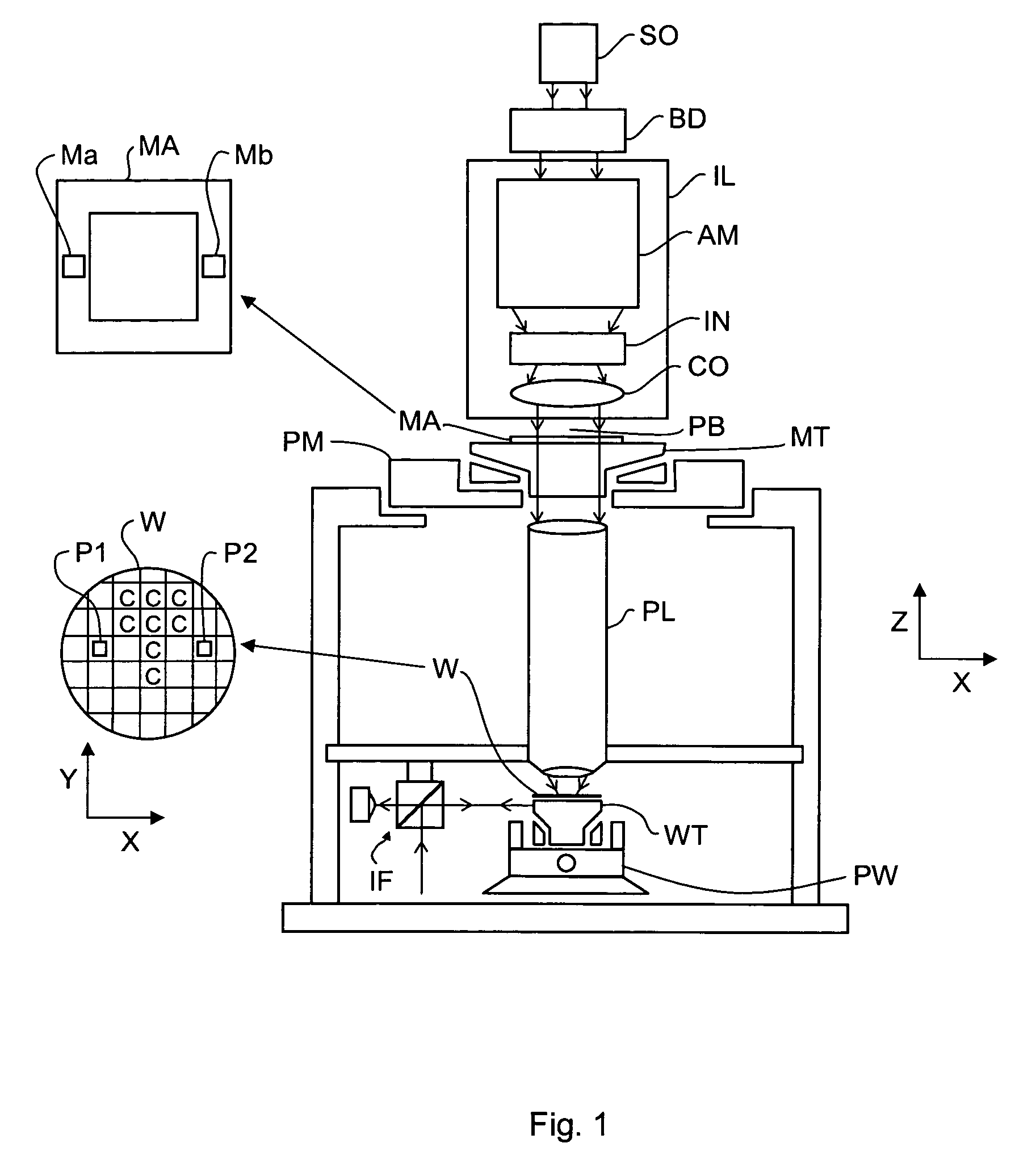
[0062]FIG. 1 schematically depicts a lithographic apparatus according to a particular embodiment of the invention. The apparatus comprises:[0063]an illumination system (illuminator) IL: for providing a projection beam PB of radiation (e.g. UV or EUV radiation).[0064]a first support structure (e.g. a mask table / holder) MT: for supporting patterning device (e.g. a mask) MA and connected to first positioning mechanism PM for accurately positioning the patterning device with respect to item PL;[0065]a substrate table (e.g. a wafer table / holder) WT: for holding a substrate (e.g. a resist-coated wafer) W and connected to second positioning mechanism PW for accurately positioning the substrate with respect to ite...


PUM

PropertyMeasurementUnit
accelerationaaaaaaaaaa
forceaaaaaaaaaa
wavelengthaaaaaaaaaa

Abstract

A positioning device for positioning an object that includes a first actuator and a connector arranged between the first actuator and the object. The connector includes a resilient member and a second actuator connected in series with the resilient member. The first actuator being constructed and arranged to exert a force in a first direction on the connector and the second actuator is controlled to maintain a distance between the first actuator and the object in the first direction substantially constant.

Description

BACKGROUND OF THE INVENTION[0001]1. Field of the Invention[0002]The present invention relates to a positioning device for positioning an object and an associated device manufacturing method.[0003]2. Description of the Related Art[0004]Lithographic apparatus can be used, for example, in the manufacture of integrated circuits (ICs). In such a case, a patterning device may be used to generate a desired circuit pattern corresponding to an individual layer of the IC, and this pattern can be imaged onto a target portion (e.g. comprising one or more dies) on a substrate (silicon wafer) that has been coated with a layer of radiation-sensitive material (resist).[0005]In general, a single substrate will contain a network of adjacent target portions that are successively exposed. Known lithographic apparatus include so-called steppers, in which each target portion is irradiated by exposing an entire pattern onto the target portion in one go, and so-called scanners, in which each target portion...

Claims


Application Information

Patent Timeline
Patent Type & Authority Patents(United States)
IPC IPC(8): G03B27/58G03B27/42G03B27/62G03F7/20
CPCG03F7/70141G03F7/70258G03F7/70758
Inventor BUTLER, HANS
Owner ASML NETHERLANDS BV
Why Eureka
Try Eureka