Compliant swage
a technology of swage and swage, applied in the field of tubular expansion, can solve the problems of reducing the diameter of swage symmetrically and the cross-sectional area beyond
- Summary
- Abstract
- Description
- Claims
- Application Information
AI Technical Summary
Benefits of technology
Problems solved by technology
Method used
Image
Examples
Embodiment Construction
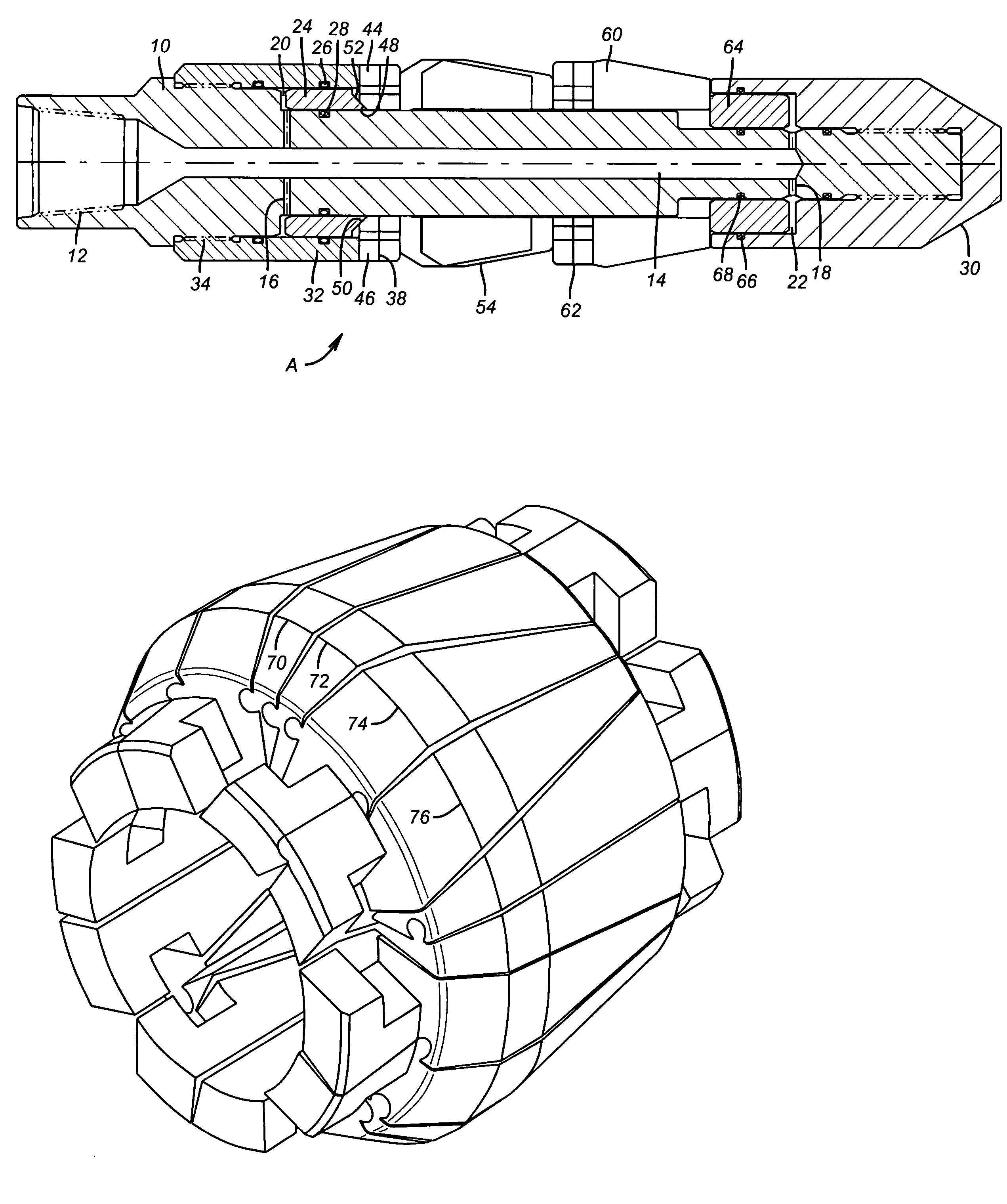
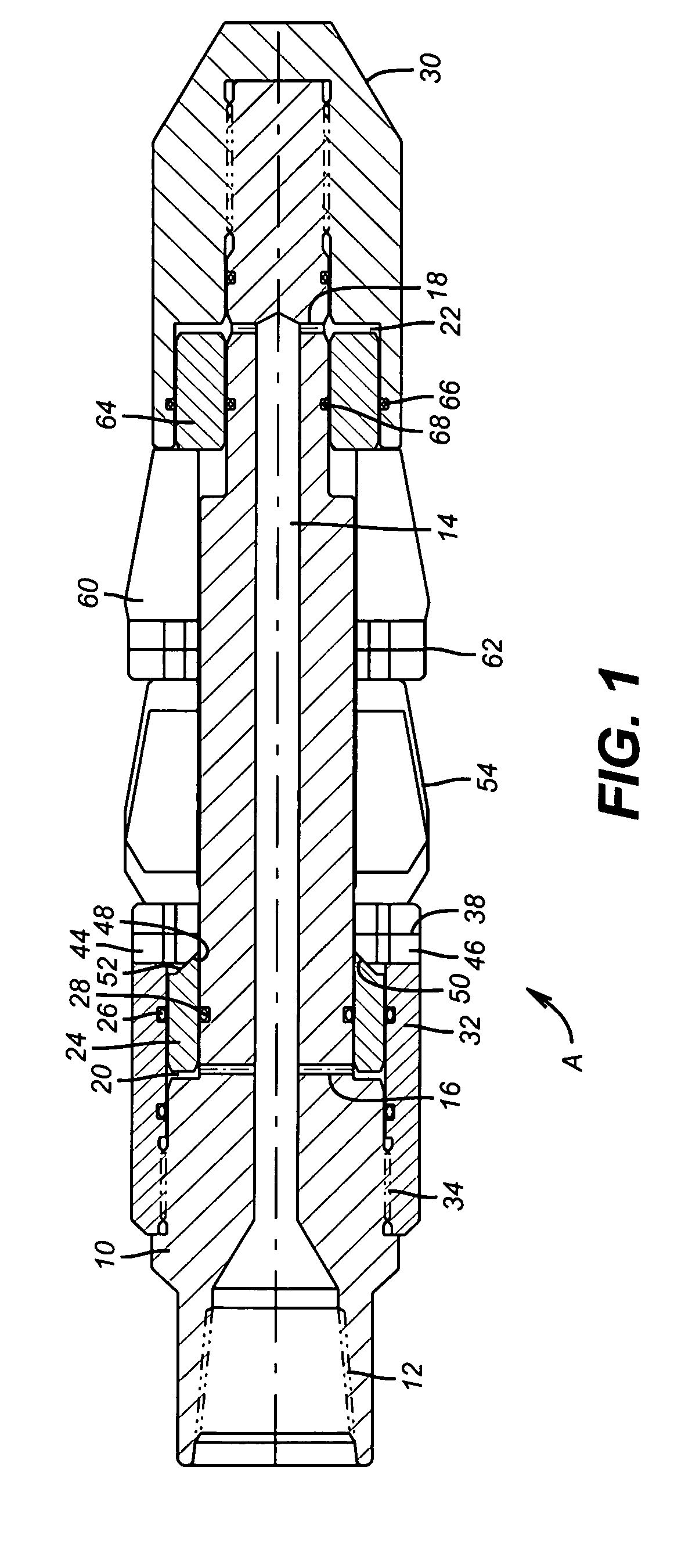
[0022]FIG. 1 shows the preferred embodiment of the swage apparatus A of the present invention. It has a mandrel 10 with thread 12 for connecting tubing or some other driving mechanism (not shown). Passage 14 has lateral exits 16 and 18 to communicate applied pressure to annular cavities 20 and 22 respectively. Rounding piston 24 is sealed by seals 26 and 28 so that pressure in cavity 20 urges rounding piston 24 toward lower end 30 of the apparatus A. Swage anchor 32 is held at thread 34 to mandrel 10. Near its lower end 36 there are a plurality of preferably T-shaped openings 38, although other shapes can be used.
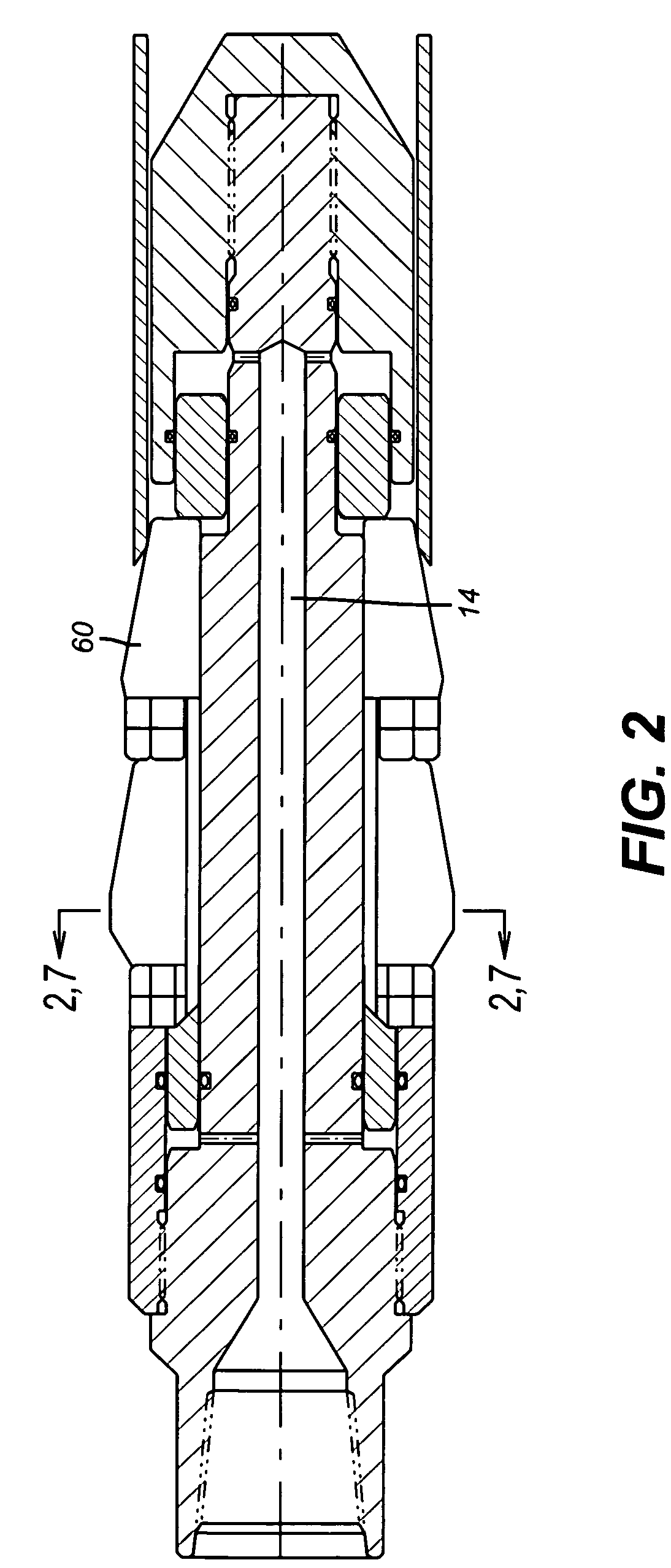
[0023]Referring to FIG. 3 swage segments 40 and 42 have C-shaped upper ends 44 and 46 respectively so that when brought together the adjacent upper ends 44 and 46 take on a T-shape that is designed to fit loosely in T-shaped openings 38 in swage anchor 32. Referring to FIGS. 1 and 9, it can be seen that upper ends 44 and 46 respectively include beveled surfaces 48 and 50 on...
PUM
| Property | Measurement | Unit |
|---|---|---|
| Angle | aaaaa | aaaaa |
| Pressure | aaaaa | aaaaa |
| Diameter | aaaaa | aaaaa |
Abstract
Description
Claims
Application Information
 - R&D
- Intellectual Property
- Life Sciences
- Materials
- Tech Scout
- Unparalleled Data Quality
- Higher Quality Content
- 60% Fewer Hallucinations
Browse by: Latest US Patents, China's latest patents, Technical Efficacy Thesaurus, Application Domain, Technology Topic, Popular Technical Reports.
© 2025 PatSnap. All rights reserved.Legal|Privacy policy|Modern Slavery Act Transparency Statement|Sitemap|About US| Contact US: help@patsnap.com


