
Snagless telecommunications plug assembly

a technology for telecommunications and plug assemblies, which is applied in the direction of coupling devices, two-part coupling devices, electrical equipment, etc., can solve the problems of difficult removal of plug assemblies, difficult inserting of plug assemblies into receiving jack assemblies, and extremely limited space, so as to achieve quick and easy disengagement

Active Publication Date: 2006-10-31
HUBBELL INC
View PDF12 Cites 5 Cited by
  • Summary
  • Abstract
  • Description
  • Claims
  • Application Information

AI Technical Summary

Benefits of technology

[0008]Accordingly, another objective of the present invention is to provide a snagless telecommunications plug assembly that prevents snagging of the plug latch upon withdrawal of the plug assembly from a receiving jack assembly.
[0009]Accordingly, another objective of the present invention is to provide a snagless telecommunications plug assembly in which the plug latch is easily accessible to quickly and easily disengage the plug assembly from a receiving jack assembly.
[0010]Accordingly, another object of the present invention is to provide a plug latch that extends above first and second ears on the plug body to provide easy access to the plug latch.
[0011]The foregoing objects are basically attained by providing a snagless telecommunications connector assembly, including a connector housing having front and rear ends, and an upper surface extending between the front and rear ends. A latch beam extends rearwardly from the front end of the connector housing over the upper surface. The latch beam is deflectable to disengage the connector assembly from a mated connection. First and second ears extend outwardly from the upper surface of the connector housing. Each of the first and second ears has a portion tapering toward the rear end of the housing. A rib extends outwardly from the latch beam. The first and second ears and the rib prevent the latch beam of the plug from becoming snagged during movement of the plug.

Problems solved by technology

Such connections are often made in areas of trunking or patch panels, where space is extremely limited.
The areas in which these connections are made have numerous wires or cables, electrical components and other electrical equipment that make inserting the plug assemblies into receiving jack assemblies difficult.
Removal of the plug assemblies is also difficult due to the numerous wires, electrical components and other equipment that interfere with accessing the plug and removing the plug from the receiving jack assembly and through the associated wires, and electrical components and equipment.
One problem with existing telecommunications plug assemblies is that the plug latch tends to catch or snag other electrical wires, electrical components or other miscellaneous electrical equipment during the drawback of the plug assembly.
The limited space within which all the wires, components and equipment must be installed creates a tight area through which the plug assembly must be drawn.
If the snagged plug latch is continuously pulled in an attempt to free the plug assembly the latch can break, thereby ruining the plug assembly.
Another problem with existing telecommunications plug assemblies is that it is difficult to access the plug latch to disengage the plug assembly from the complementary jack assembly.
The numerous electrical wires, electrical components and other electrical equipment make it difficult to access and depress the latch to remove the plug assembly.
Some existing telecommunications plug assemblies have snagless features that increase the difficulty of accessing and depressing the latch to remove the plug assembly.
The latch beam being positioned between two higher ears makes it difficult for the user's finger to get between the two ears to depress the plug latch sufficiently to disengage the plug assembly from the receiving jack assembly.
Thus, the ears increase the difficulty of accessing and depressing the latch beam.

Method used


Image

  • Snagless telecommunications plug assembly
  • Snagless telecommunications plug assembly
  • Snagless telecommunications plug assembly

Examples


Embodiment Construction

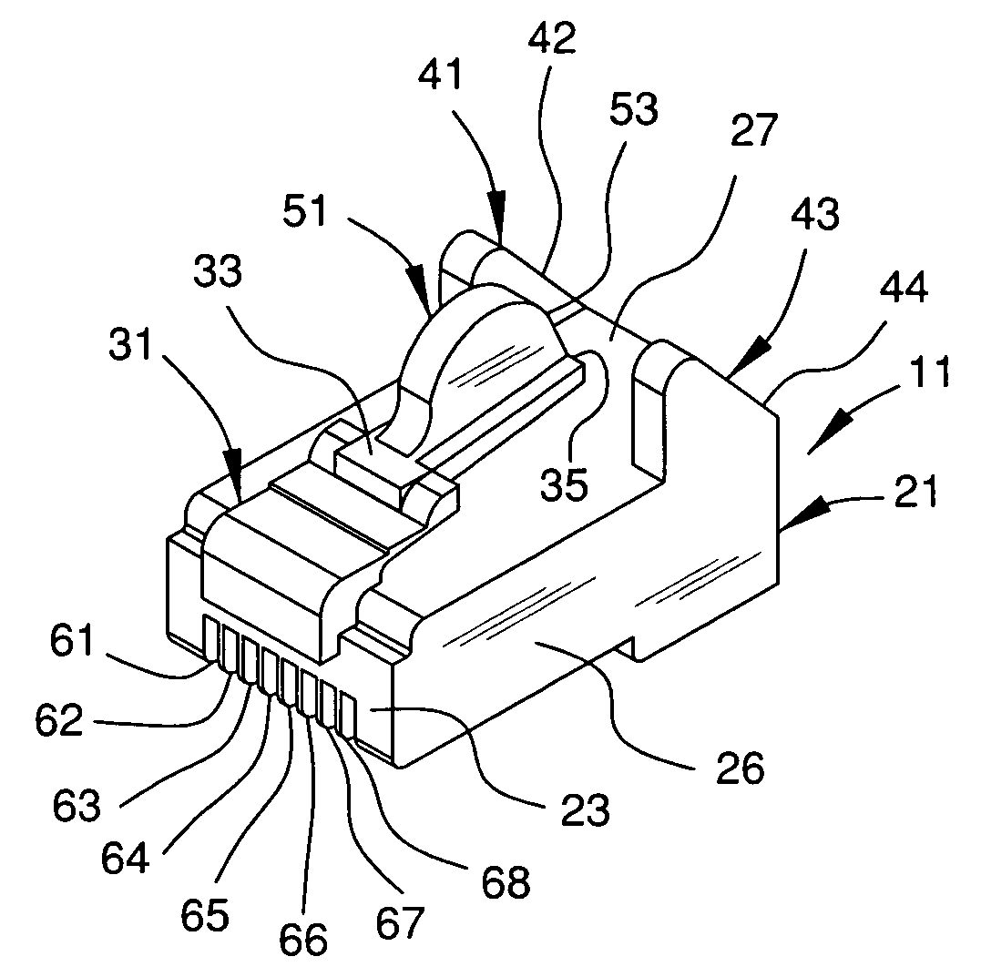
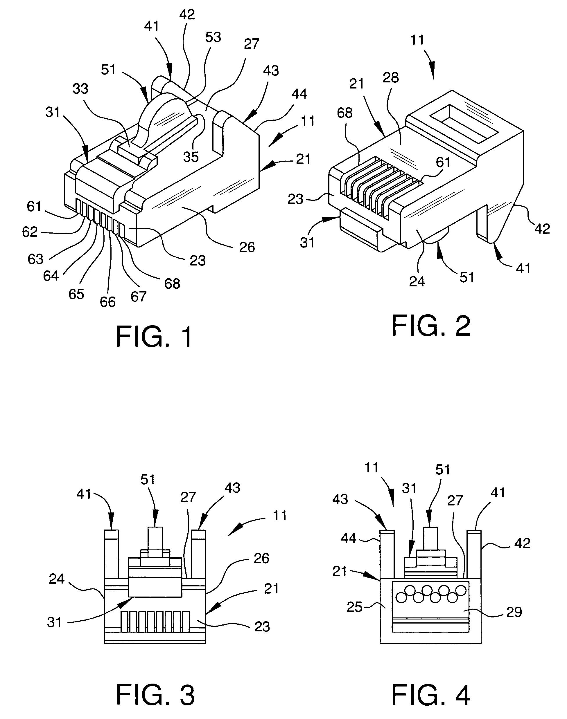
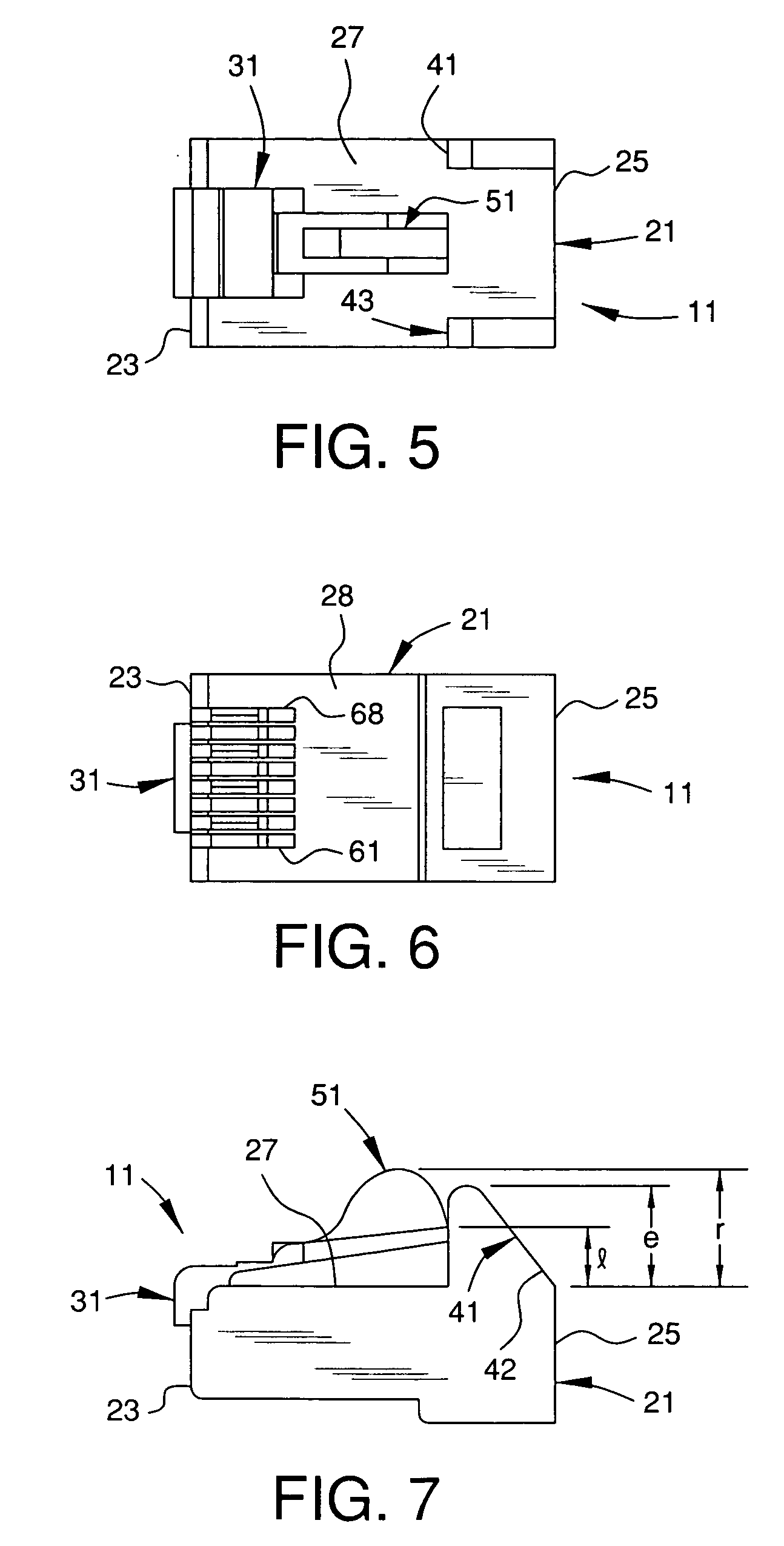
[0028]As shown in FIGS. 1–14, a snagless telecommunications connector assembly 11 has a connector housing 21 having a front end 23 and a rear end 25. An upper surface 27 extends between the front and rear ends. A latch beam 31 extends rearwardly from the front end 23 of the connector housing 21 adjacent to and over upper surface 27. The latch beam 31 is deflectable to disengage the connector assembly 11 from a mated connection. A first ear 41 and a second ear 43 extend outwardly from the upper surface 27 of the connector housing 21. Each of the first and second ears 41 and 43 has a portion tapering toward the rear end 25 of the housing 21. A rib 51 extends outwardly from the latch beam 31. The first and second ears 41 and 43 and the rib 51 prevent the latch beam 31 of the connector assembly 11 from becoming snagged during withdrawing movement of the connector assembly.

[0029]Preferably, the present invention relates to a modular plug assembly 11 for use in a 4, 6, 8 or 10 position in...


PUM


Abstract

A snagless telecommunications connector assembly is quickly and easily disengageable from a complementary mating connector assembly. A connector housing has front and rear ends, and an upper surface extending between the front and rear ends adjacent and above the upper surface. A latch beam extends rearwardly from the front end of the connector housing. The latch beam is deflectable to disengage the connector assembly from a complementary mating connector assembly. First and second ears extend outwardly from the upper surface of the connector housing. Each of the first and second ears has a portion tapering toward the rear end of the housing to prevent snagging the latch beam. A rib extends outwardly from the latch beam to further prevent snagging of the latch beam.

Description

FIELD OF THE INVENTION [0001]The present invention relates to a snagless telecommunications connector assembly. More particularly, the present invention relates to a snagless telecommunications plug assembly having first and second ears on the plug body and a rib on a latch beam between the first and second ears. Still more particularly, the present invention relates to a telecommunications plug assembly in which a rib on a latch beam extends above the highest point of first and second ears on the plug body. The snagless telecommunications plug assembly facilitates removing the plug assembly without catching or snagging the latch beam on adjacent wiring or cables.BACKGROUND OF THE INVENTION [0002]In telecommunication systems, signals are transmitted over cables having a plug assembly at one end connected to a complementary mating connector. Such connections are often made in areas of trunking or patch panels, where space is extremely limited. The areas in which these connections are...

Claims


Application Information

Patent Timeline
Patent Type & Authority Patents(United States)
IPC IPC(8): H01R13/625H01R4/50H01R13/627
CPCH01R13/6272H01R2201/16H01R24/64
Inventor O'CONNOR, DOUGLAS P.KIERSTEAD, GLENN T.
Owner HUBBELL INC
Learn More