Grinder capable of seizing rotary shaft

a rotary shaft and grinder technology, applied in the field of grinders, can solve the problems of damage to the grinder, inconvenient operation of two wrenches at the same time, and inability to touch the button above the chucking press button in operation, so as to avoid damage to the grinder

Inactive Publication Date: 2006-10-31
GISON MASCH CO LTD
View PDF14 Cites 39 Cited by
  • Summary
  • Abstract
  • Description
  • Claims
  • Application Information

AI Technical Summary

Benefits of technology

[0006]It is therefore a primary object of the present invention to provide a grinder capable of seizing rotary shaft. The grinder is equipped with a press button unit for chucking the rotary shaft of the grinder. The press button must be first turned and then pressed for seizing the rotary shaft. In case the press button unit is unexpectedly or incautiously mis-touched in operation, the rotary shaft will not be suddenly seized. This avoids damage of the grinder.

Problems solved by technology

It is inconvenient to operate two wrenches at the same time.
However, the above chucking press button is often incautiously mis-touched in operation.
This will lead to damage of the grinder.

Method used


Image

  • Grinder capable of seizing rotary shaft
  • Grinder capable of seizing rotary shaft
  • Grinder capable of seizing rotary shaft

Examples


Embodiment Construction

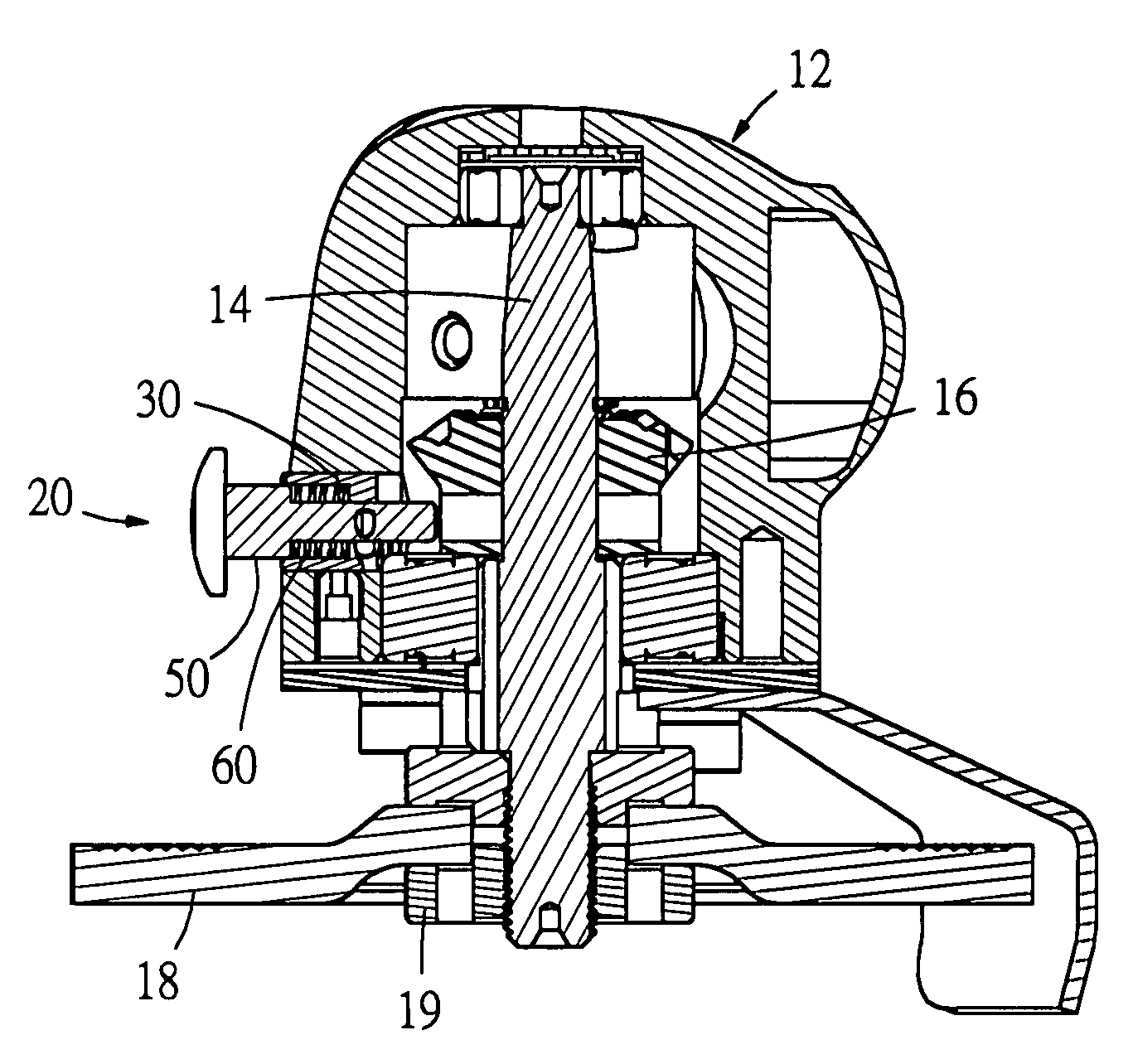
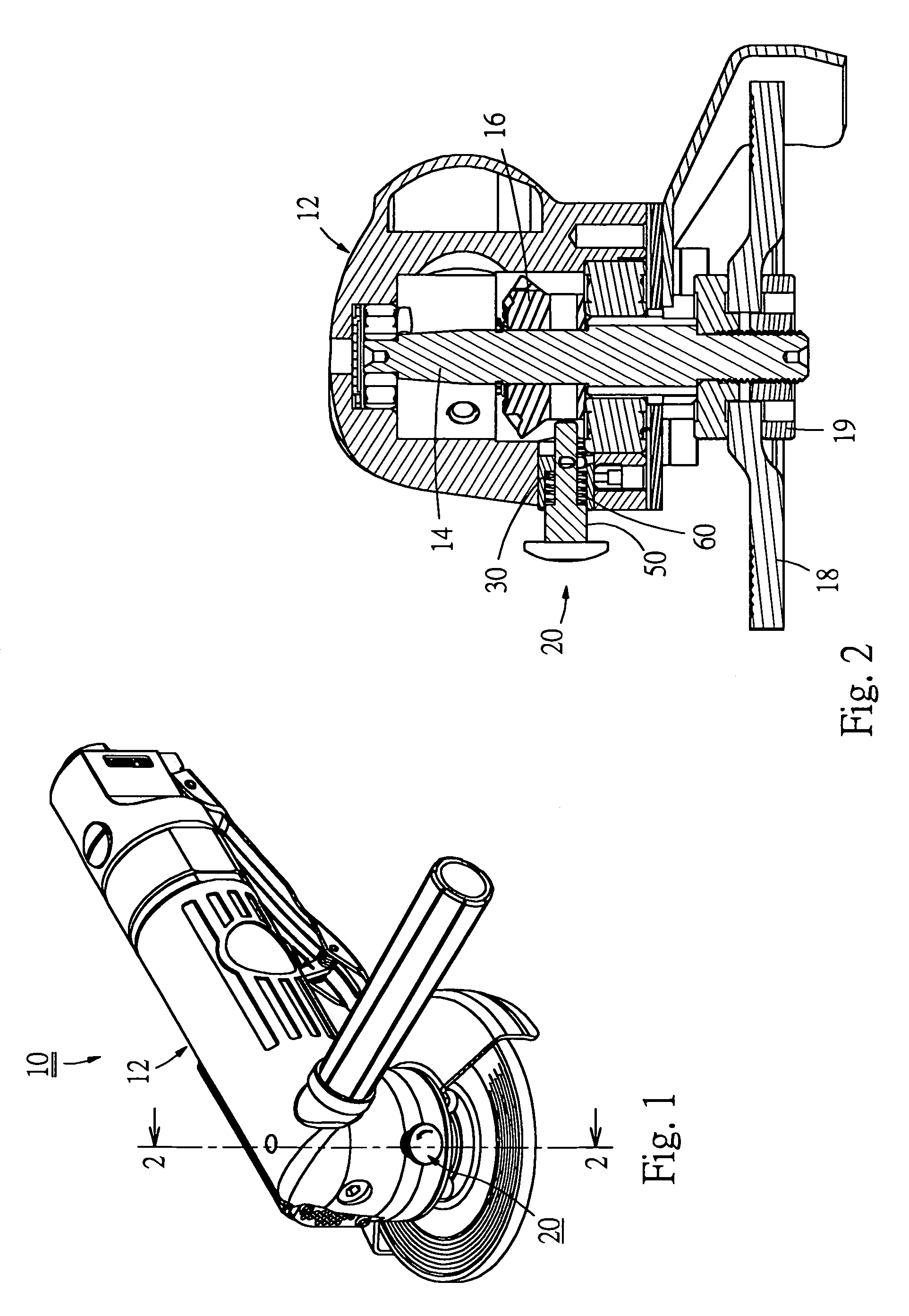
[0027]Please refer to FIGS. 1 and 2. According to a preferred embodiment, the grinder 10 of the present invention can be a pneumatic grinder or an electric grinder. A driving shaft is disposed in the housing 12 of the grinder 10 and drivable by a driving mechanism. (In the case of pneumatic grinder, the driving mechanism is a rotor, while in the case of electric grinder, the driving mechanism is a motor.) The driving shaft serves to drive a rotary shaft 14. In this embodiment, the driving shaft is drivingly engaged with the rotary shaft 14 via bevel gears 16. A grinding disc 18 is fitted at bottom end of the rotary shaft 14 and tightened with a nut 19. A press button unit 20 is arranged on the housing 12 for chucking the rotary shaft 14.

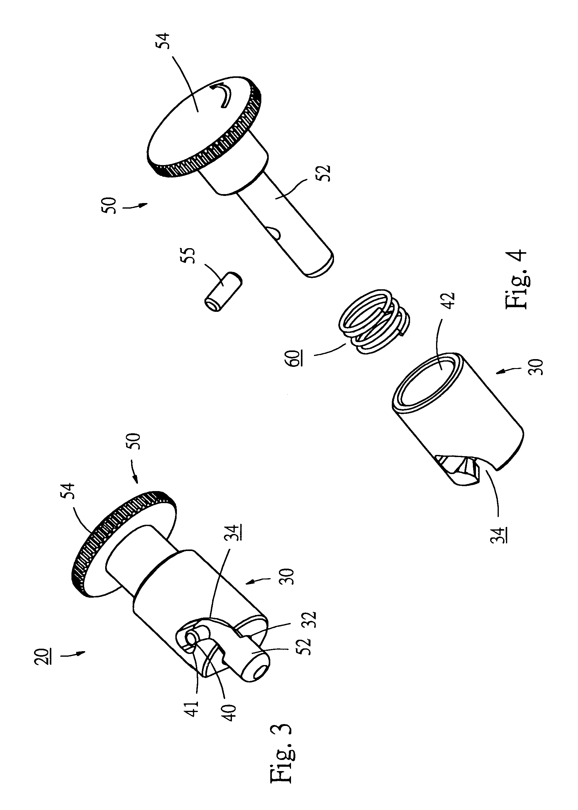
[0028]Referring to FIGS. 3 to 5, the press button unit 20 includes a cylindrical button seat 30, a press button member and a resilient mechanism.

[0029]The cylindrical button seat 30 is formed with an axial tunnel 32 passing through the button seat 30...


PUM


Abstract

A grinder having a rotary shaft and a grinding disc mounted at a bottom end of the rotary shaft for grinding a work piece. A press button unit is disposed on a housing of the grinder. By means of pressing the press button unit, the rotary shaft of the grinder can be seized for replacement of the grinding disc. Before pressing the press button unit, a user must first angularly displace the press button unit. That is, the press button unit cannot be directly pressed without being first turned by a certain angle. Therefore, in operation, mis-touch of the press button unit can be avoided so as to avoid damage of the grinder.

Description

BACKGROUND OF THE INVENTION[0001]The present invention is related to a grinding apparatus, and more particularly to a grinder having a press button. By means of pressing the press button, the rotary shaft of the grinder can be seized for replacement of the grinding disc. The press button is prevented from being mis-touched by a user so as to avoid damage of the grinder.[0002]A conventional grinder such as a pneumatic grinder or an electric grinder is equipped with a grinding disc at bottom end for grinding a work piece.[0003]When replacing the grinding disc, a user needs to chuck the rotary shaft with one wrench and wrench the nut at bottom end of the rotary shaft with another wrench. After the nut is untightened, the original grinding disc can be taken off and a new grinding disc can be fitted on the rotary shaft. Then the nut is retightened to fix the new grinding disc.[0004]It is inconvenient to operate two wrenches at the same time. In order to solve this problem, an improved gr...

Claims


Application Information

Patent Timeline
Patent Type & Authority Patents(United States)
IPC IPC(8): B24B23/00
CPCB24B23/022
Inventor LIN, FREDDY
Owner GISON MASCH CO LTD
Why Eureka
Try Eureka