Joystick controller

a joystick controller and controller technology, applied in the direction of mechanical control devices, manual control with single controlling member, limiting/preventing/returning movement of parts, etc., can solve the problems of only being able to achieve the pivotal movement of the joystick in the other direction about the orthogonal y-axis, and overriding the vertical control

Inactive Publication Date: 2006-10-31
PENNY & GILES CONTROLS
View PDF14 Cites 7 Cited by
  • Summary
  • Abstract
  • Description
  • Claims
  • Application Information

AI Technical Summary

Benefits of technology

[0008]It is an aim of the present invention to provide a joystick controller that alleviates the aforementioned problems.
[0015]The profiled surface of the seat member may have a profile that has a wave-like form. The wave-like form may approximate to a sine wave. The corresponding surface of the slider member may include at least a portion having a corresponding profile. It is an advantage that the wave-like form provides lock positions defined by the troughs of the waves.
[0016]Preferably, the wave-like form of the profiled surface of the seat member has a plurality of troughs defining a plurality of lock positions. It is a further advantage that the wave-like forms provide continuous smooth contacting surfaces between the slider member and the seat member so that movement of the lever out of a lock position, or from one lock position to another, can be done smoothly.
[0021]Embodiments of this aspect may include a brake means for providing a frictional force to resist movement of the lever about the first axis. It is an advantage that the frictional force adds to the biasing force to help ensure that the joystick lever stays at the “put and stay” angle until moved to a different angle by the operator.

Problems solved by technology

When the joystick is locked, the vertical controls are over-ridden.
A problem with this arrangement is that, when in the locked position, pivotal movement of the joystick in the other direction about the orthogonal y-axis can only be achieved by a corresponding pivotal movement of the bush and cradle.
It is a problem to achieve this while still retaining the return-to-centre feature in the orthogonal y direction.

Method used


Image

  • Joystick controller
  • Joystick controller
  • Joystick controller

Examples


Embodiment Construction

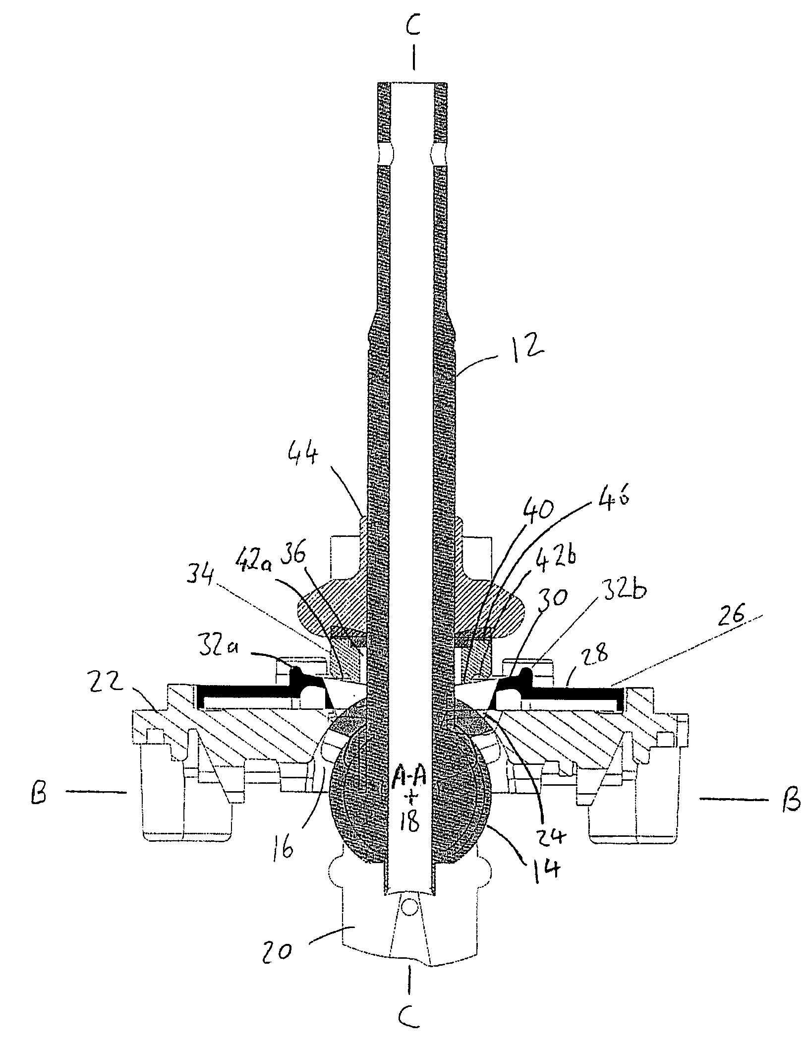
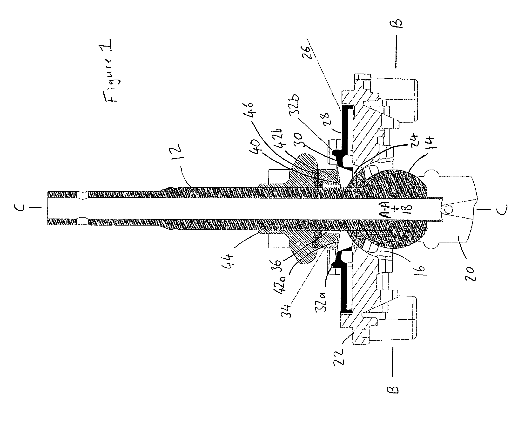
[0035]Referring to FIG. 1, a joystick controller 10 of the ball and socket type, has a lever 12 mounted to a ball 14, which is located in a part-spherical socket 16, allowing universal pivotal movement between the ball 14 and the socket 16 about a pivot centre 18. The pivot centre 18 is at the intersection of a first axis A—A, orthogonal to the plane of the page of FIG. 1, a second axis B—B, and a third axis C—C that defines an axis of the lever 12. The lever 12 extends past the pivot centre 18 to an armature 20. The armature 20 carries part of one or more movement detection devices (not shown) for providing output signals indicative of the pivotal movement of the lever 12. Examples of suitable movement detection devices include potentiometers or non-contact devices such as Hall effect sensors.

[0036]The socket 16 forms part of a housing, of which only a top portion 22 is shown in FIG. 1. The top portion 22 has a central opening 24 through which the lever 12 extends. The central open...


PUM


Abstract

A joystick controller has a lever mounted for pivotal movement relative to a housing, a seat member affixed to the housing, and a slider member biased towards the seat member. The seat member has a profiled surface that cooperates with a corresponding surface of the slider member. In one aspect, the profiled surface includes at least one lock position for engaging the slider member at a predetermined angle of pivotal displacement of the lever about a first axis. The slider member is shaped to allow pivotal movement of the lever about a second axis, without movement of the slider member, but to prevent movement of the lever about the first axis when engaged in the lock position. In another aspect, the profiled surface has a profile in a first direction whereby the biasing force remains substantially constant when the lever is pivotally displaced about a first axis, and a profile in a second direction whereby displacement of the lever about a second axis displaces the slider member so as to alter the biasing force.

Description

CROSS REFERENCE TO RELATED APPLICATION[0001]This application relates to and claims priority to corresponding Great Britain Patent Application No. 0503663.7, which was filed on Feb. 23, 2005, and which is incorporated by reference herein.TECHNICAL FIELD[0002]The present invention relates to Joystick controllers.BACKGROUND OF THE INVENTION[0003]Joystick controllers are used in a wide variety of control applications. One example is in the control of an excavator bucket. Movement of the bucket is actuated by hydraulic pistons, which are controlled by electrical signals provided by the joystick. The joystick has a lever, which is mounted for pivotal movement relative to a fixed body. Movement of the lever in one direction, by pivoting the lever about a first axis, controls the raising and lowering of the bucket. Movement of the lever in a second direction, by pivoting about a second axis (usually orthogonal to the first axis), controls orientation of the bucket (i.e. moves the bucket by ...

Claims


Application Information

Patent Timeline
Patent Type & Authority Patents(United States)
IPC IPC(8): H01H25/04G05G5/04G05G9/047
CPCG05G5/04G05G9/047G05G2009/04707G05G2009/04714
Inventor EDMUNDS, WAYNE
Owner PENNY & GILES CONTROLS
Why Eureka
Try Eureka