Valve timing changer

a timing change and valve technology, applied in the direction of valve details, valve arrangements, valve drives, etc., can solve the problem of compact apparatus, and achieve the effect of reducing engine load and reducing energy to supply lubricating oil

Inactive Publication Date: 2006-11-07
MIKUNI CORP
View PDF13 Cites 2 Cited by
  • Summary
  • Abstract
  • Description
  • Claims
  • Application Information

AI Technical Summary

Benefits of technology

[0010]With this structure, when the drive member operates, relative rotation is generated at the oil pressure generating mechanism, and oil pressure is generated. The angle change mechanism is driven by the oil pressure, and the angular position of the cam shaft in the rotating direction is changed against the rotational drive member (for example, a sprocket, a timing pulley or the like). In this manner, the open-close timing of the valve is changed in accordance with engine conditions. Particularly, by adopting the oil pressure generating mechanism and the drive member, simplification and downsizing of the structure is obtained, and engine load is reduced, and oil pressure drop is suppressed. Therefore, a plurality of the apparatuses can be mounted on an engine. Further, change operation of open-close timing of a valve can be reliably performed at all drive modes of an engine.
[0026]With this structure, engine lubricating oil is supplied to the angle change mechanism as the operating oil. Since the oil pressure generating mechanism generates oil pressure separately, the energy to supply the lubricating oil can be reduced relative to that of a conventional case, and engine load can be reduced.

Problems solved by technology

Further, since each structural part is aggregated towards the axis of the cam shaft, the apparatus becomes compact.

Method used


Image

  • Valve timing changer
  • Valve timing changer
  • Valve timing changer

Examples


Embodiment Construction

[0032]The embodiments of the present invention are explained in the following with reference to the attached drawings.

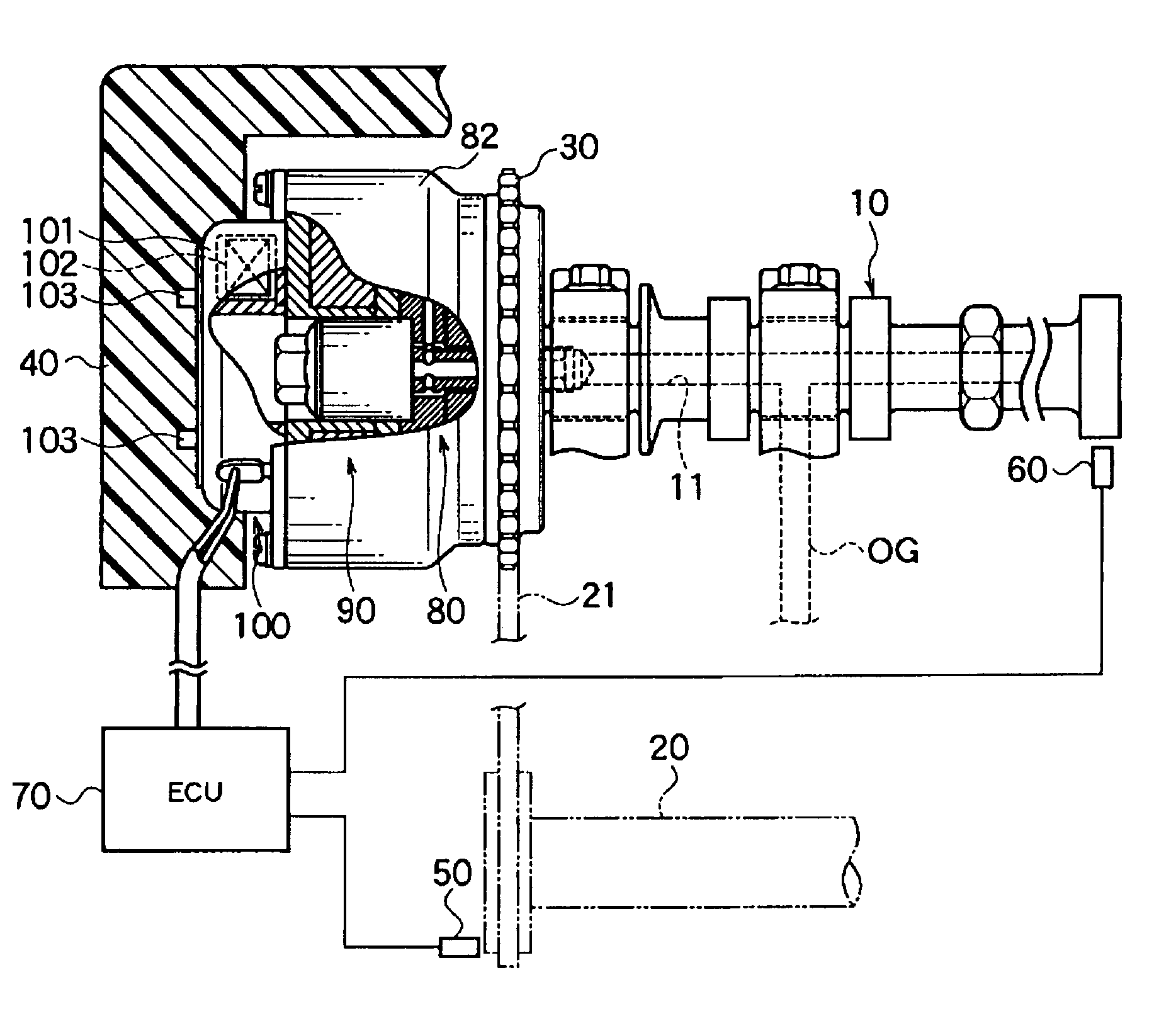
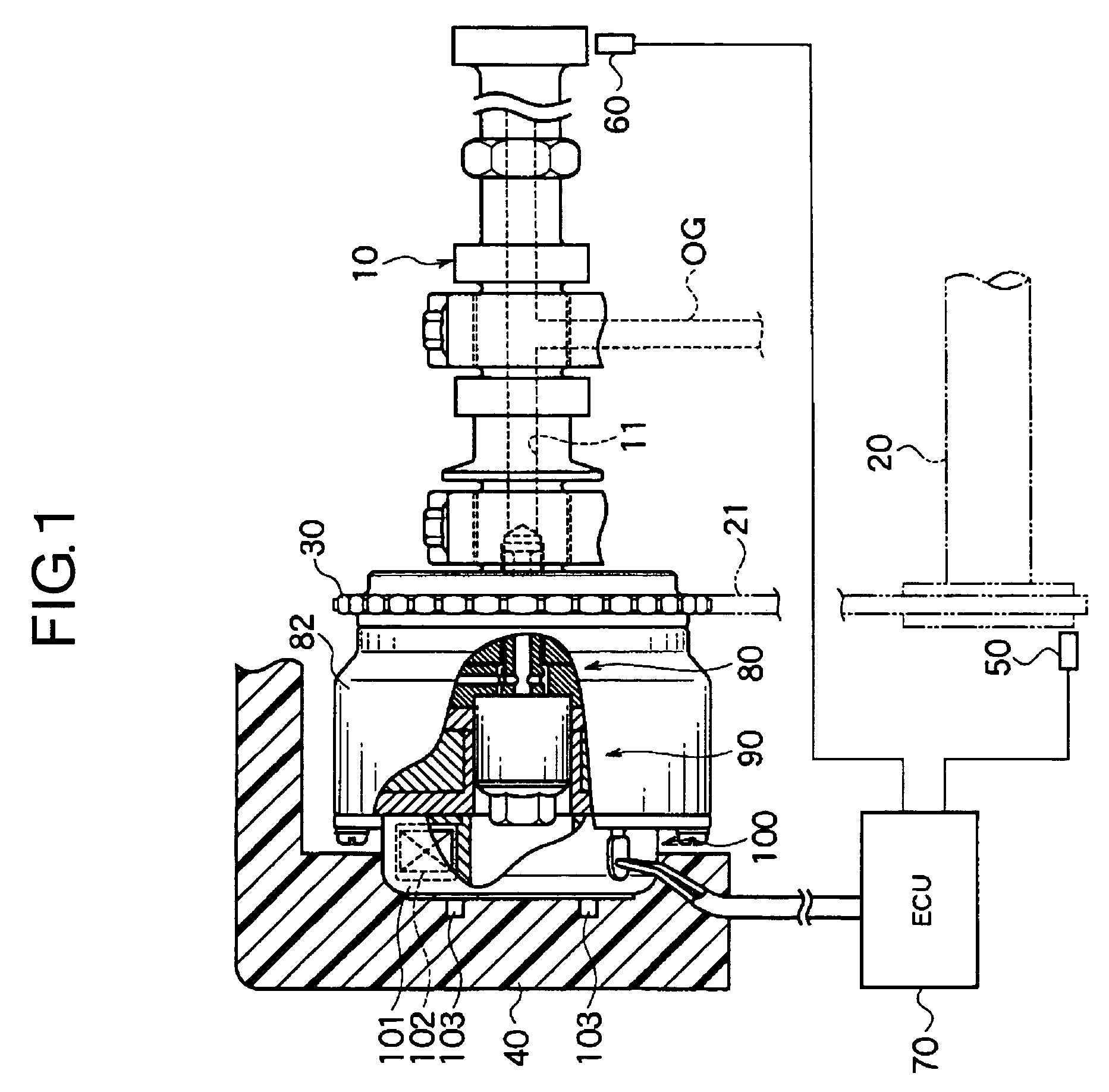
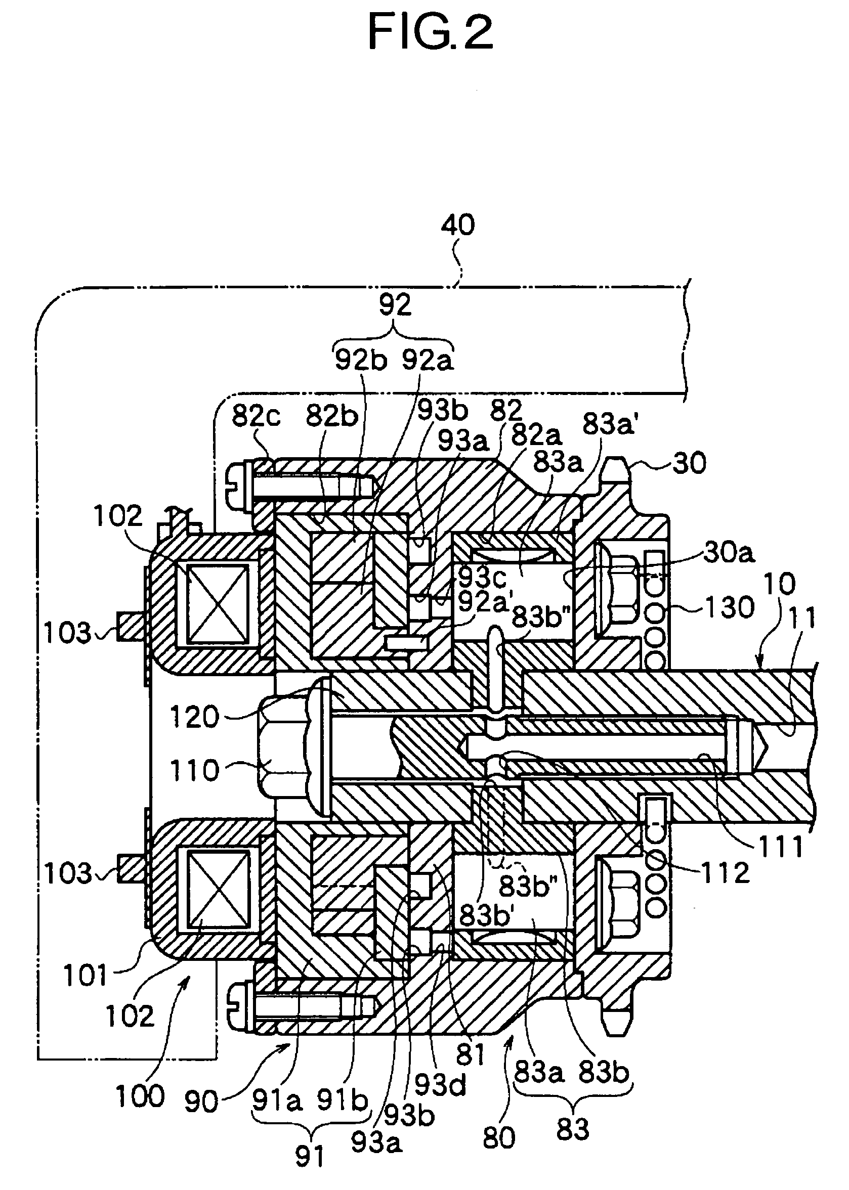
[0033]FIGS. 1 through 5(b) show an embodiment of a valve timing change apparatus of the present invention. FIG. 1 is an abbreviated schematic drawing. FIG. 2 is a sectional view of a main part. FIG. 3 is a rear view of an oil pressure generating mechanism. FIGS. 4(a)–(f) are front and rear views of component parts of the oil pressure generating mechanism. FIGS. 5(a) and (b) are a front view and a rear view of an angle change mechanism.

[0034]As shown in FIG. 1, an internal combustion engine to which the apparatus is mounted comprises a cam shaft 10 driving an intake valve or an exhaust valve, a crank shaft 20 making a piston reciprocate, a chain 21 transmitting rotational drive force of the crank shaft 20 to the cam shaft 10, a sprocket 30 as a rotational drive member, a cylinder head cover 40, a crank angle sensor 50 detecting rotational angle of the crank shaft 20, ...


PUM


Abstract

A valve timing change apparatus of the present invention is an apparatus for changing the relative angular position between a cam shaft 10 and a sprocket 30, which comprises an angle change mechanism 80 changing and holding the relative angular position between the cam shaft 10 and the sprocket 30 by oil pressure, an oil pressure generating mechanism 90 for generating oil pressure for driving the angle change mechanism 80 by relative rotation, and an electromagnetic retarder 100 for generating relative rotation at the oil pressure generating mechanism 90. With this structure, simplification and downsizing of the apparatus, reduction of engine load, suppression of oil pressure drop, etc. can be obtained. Then, a plurality of the apparatus can be mounted on an engine. In this manner, downsizing of the valve timing change apparatus, reduction of engine load, downsizing of an oil pump, etc. can be obtained.

Description

TECHNICAL FIELD[0001]The present invention relates to a valve timing change apparatus which changes the open-close timing of at least one of an intake valve and an exhaust valve of an internal combustion engine.BACKGROUND ART[0002]As a conventional valve timing change apparatus to change the open-close timing of an intake valve or an exhaust valve of an internal combustion engine, the structure which changes the rotational phases of a cam shaft to drive the intake valve or the exhaust valve and a crank shaft is known. For example, such a structure is disclosed in Japanese Patent No. 3033582, Japanese Patent laid-open 2000-274215, etc.[0003]The apparatus disclosed in Japanese Patent No. 3033582 comprises an advancing oil-pressure chamber and a retarding oil-pressure chamber disposed at both sides of a vane which rotates within a specific angle range in a housing, and a lubricating oil passage communicating with both oil-pressure chambers. Then, by a switching valve (namely, an oil co...

Claims


Application Information

Patent Timeline
Patent Type & Authority Patents(United States)
IPC IPC(8): F01L1/34F01L1/344
CPCF01L1/022F01L1/34F01L1/3442F01L1/344F01L2001/3443F01L2001/34433F01L2001/34483
Inventor TANNO, KEIJITASHIRO, MOTOMICHI
Owner MIKUNI CORP
Why Eureka
Try Eureka