

Robot
a robot and end effector technology, applied in the field of robots, can solve the problems of limited movable range of the robot arm and the robot arm having the end effector, complex and large tools, and reduce the attachment structure of the robot arm and the structure of the end effector. the effect of reducing the size of the structur
- Summary
- Abstract
- Description
- Claims
- Application Information
AI Technical Summary
Benefits of technology
Problems solved by technology
Method used
Image

Examples
first embodiment
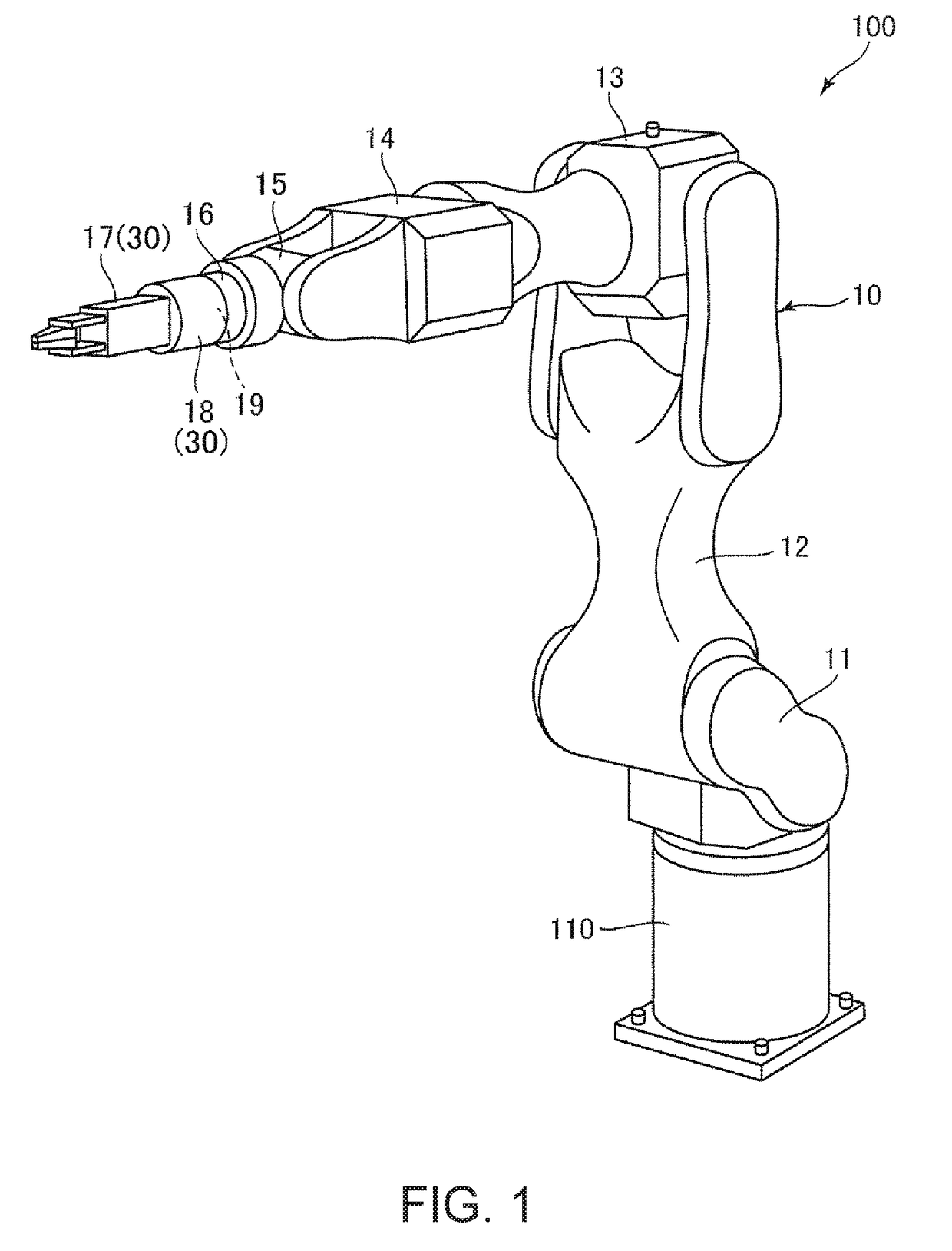
[0034]First, an outline of the robot will be explained with reference to FIG. 1.
[0035]FIG. 1 is a perspective view showing a robot according to the first embodiment of the invention.
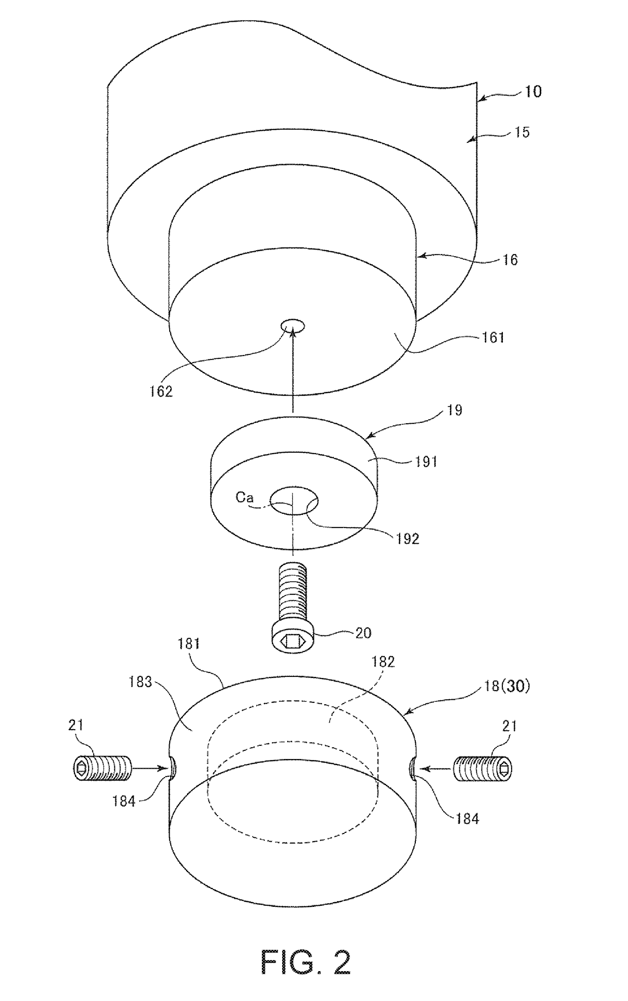
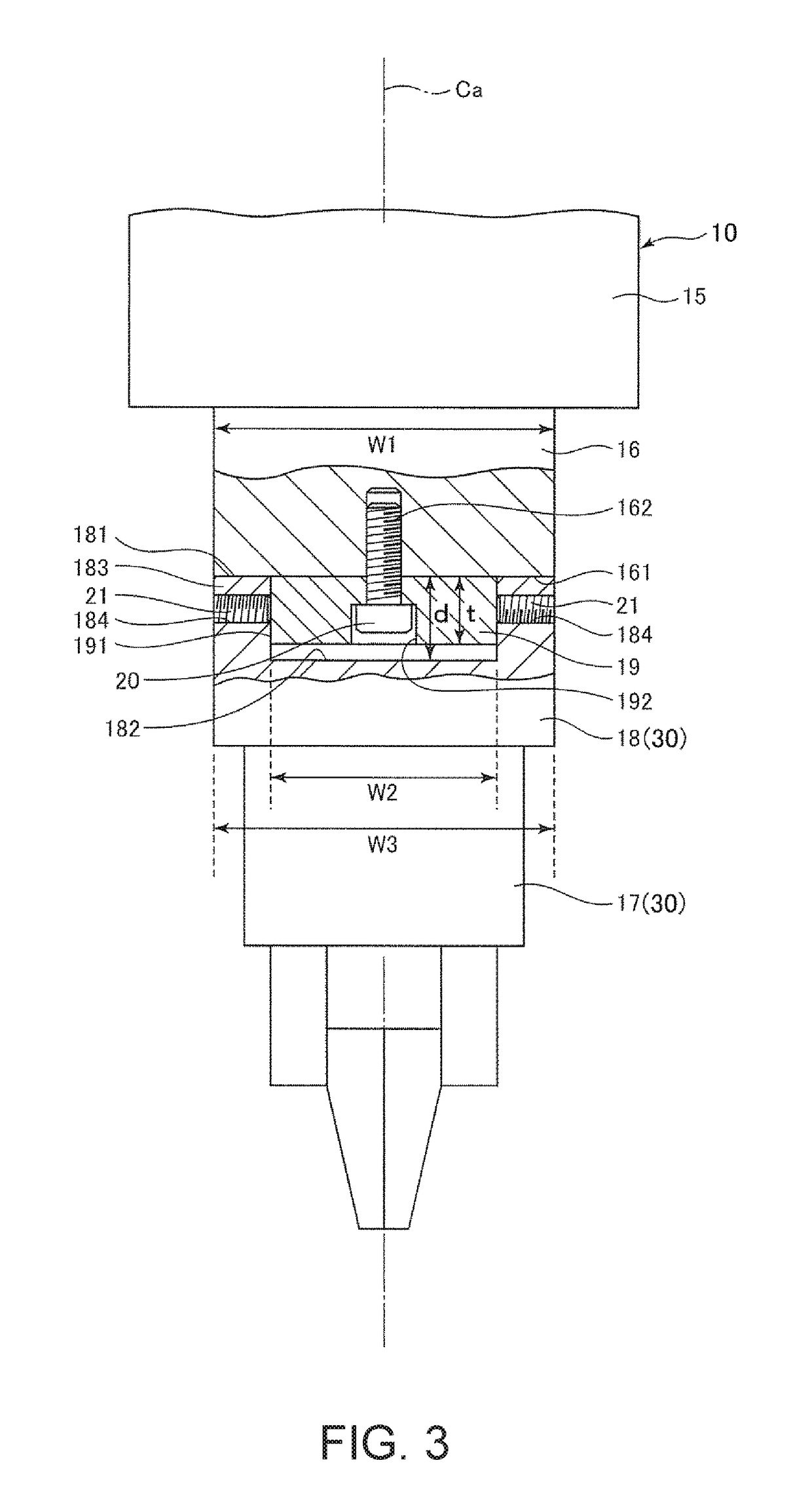
[0036]A robot 100 shown in FIG. 1 is the so-called single-arm six-axis vertical articulated robot and used for work of feeding, removing, carrying, assembly, etc. of objects including precision apparatuses and components forming the apparatuses. The robot 100 has a base 110 and a robot arm 10 rotatably coupled to the base 110. Further, an end effector 17 is attached to the robot arm 10 via a relay member 19 and a force detection sensor 18.
[0037]The base 110 is fixed to e.g. a floor, wall, ceiling, movable platform, or the like. The robot arm 10 has an arm 11 (first arm) rotatably coupled to the base 110, an arm 12 (second arm) rotatably coupled to the arm 11, an arm 13 (third arm) rotatably coupled to the arm 12, an arm 14 (fourth arm) rotatably coupled to the arm 13, an arm 15 (fifth arm) rotatably coup...
second embodiment
[0065]FIG. 4 is a partially sectional side view showing an attachment structure of a structure to a robot arm according to the second embodiment of the invention.
[0066]As below, the second embodiment will be explained with a focus on the differences from the above described embodiment and the explanation of the same items will be omitted. In FIG. 4, the same configurations as those of the above described embodiment have the same signs.
[0067]In a robot 100A shown in FIG. 4, an end effector 17A (structure 30A) is directly attached to the robot arm 10 via the relay member 19.
[0068]Here, in an end surface 171 of the end effector 17A on the robot arm 10 side, a concave portion 172 similar to the concave portion 182 of the above described first embodiment is provided. The relay member 19 is inserted into the concave portion 172.
[0069]With the concave portion 172 provided in the end surface 171, a wall portion 173 is provided in the end effector 17A. That is, the end effector 17A includes ...
third embodiment
[0076]FIG. 5 is a partially sectional side view showing an attachment structure of a structure to a robot arm according to the third embodiment of the invention. FIG. 6 is a partially sectional side view showing a fitting part in the attachment structure shown in FIG. 5.
[0077]As below, the third embodiment will be explained with a focus on the differences from the above described embodiments and the explanation of the same items will be omitted. In FIGS. 5 and 6, the same configurations as those of the above described embodiments have the same signs.
[0078]In a robot 100B shown in FIG. 5, a structure 30B is attached to the robot arm 10 via a relay member 19B. The structure 30B has a force detection sensor 18B (force detection sensor) fixed to the relay member 19B and the end effector 17 attached to the force detection sensor 18B.
[0079]Here, the force detection sensor 18B has a circular cylindrical outer shape and has two end surfaces (bottom surfaces). Further, a concave portion 182B...
PUM
 Abstract
Description
Claims
Application Information