Gas divided flow supplying apparatus for semiconductor manufacturing equipment

a technology of gas divided flow and semiconductor manufacturing equipment, which is applied in the direction of flow control using electric means, thin material processing, instruments, etc., can solve the problems of difficult control of divided flow and cost reduction, and achieve the effects of easy switching one, high accuracy of flow control, and significant simplified structure of gas divided flow supplying apparatus

Active Publication Date: 2020-01-14
FUJIKIN INC
View PDF15 Cites 2 Cited by
  • Summary
  • Abstract
  • Description
  • Claims
  • Application Information

AI Technical Summary

Benefits of technology

[0029]According to the present invention, by one pressure type flow control unit or one pressure type flow control unit and one thermal type flow control unit, a process gas is supplied to a plurality of process chambers through a plurality of orifices connected in parallel, so that the structure of the gas divided flow supplying apparatus can be significantly simplified, downsized and compactified. When the plurality of orifices are the same orifice, divided flows at the same flow rate of the process gas can be simultaneously supplied to the plurality of process chambers that perform the same process, so that the gas divided flow supplying apparatus can be further downsized.
[0030]In addition, respective members constituting the gas divided flow supplying apparatus are integrally assembled in one body, so that the gas divided flow supplying apparatus can be significantly downsized.
[0031]Further, opening and closing of the respective branched pipe passage opening and closing valves are controlled from the arithmetic and control unit, so that the process gas can be supplied to only an arbitrary branched pipe passage (or passages), and the branched pipe passage to which the gas is supplied can be easily switched one another.
[0032]In addition, the thermal type flow control unit is provided, so that highly accurate flow control can be performed even for a process gas under a non-critical expansion condition, and even during flow control by the pressure type flow control unit under the critical expansion condition, the actual flow rate can be appropriately checked by using the thermal type flow control unit.

Problems solved by technology

Specifically, the problems with the background systems are, (a) downsizing and reductions in the cost of the gas supplying apparatus are difficult when the pressure type flow control system is provided for each gas supply line (each divided flow line), (b) when the primary side pressure P1 of each orifice is regulated by an automatic pressure controller provided on the gas supply source side, and the respective divided gas flow rates Q1, Q2 in proportion to the pressure P1 are supplied through the respective orifices, assembling and manufacturing of the gas supplying apparatus are troublesome and downsizing and compactification of the apparatus are difficult, when any of the divided flow passages is opened or closed, the orifice primary side pressure P1 fluctuates and the divided flow rate of the other divided flow passage (or passages) easily fluctuates, and it becomes difficult to control the divided flow rates Q1, Q2 with high accuracy when the ratio P1 / P2 of the orifice primary side pressure P1 to the secondary side pressure P2 becomes a value (for example, approximately 2 or less in the case of O2 or N2) out of the critical expansion condition, etc.

Method used


Image

  • Gas divided flow supplying apparatus for semiconductor manufacturing equipment
  • Gas divided flow supplying apparatus for semiconductor manufacturing equipment
  • Gas divided flow supplying apparatus for semiconductor manufacturing equipment

Examples


Embodiment Construction

[0041]Hereinafter, preferred embodiments of the present invention are described based on the drawings, in which like parts are indicated by like reference numerals.

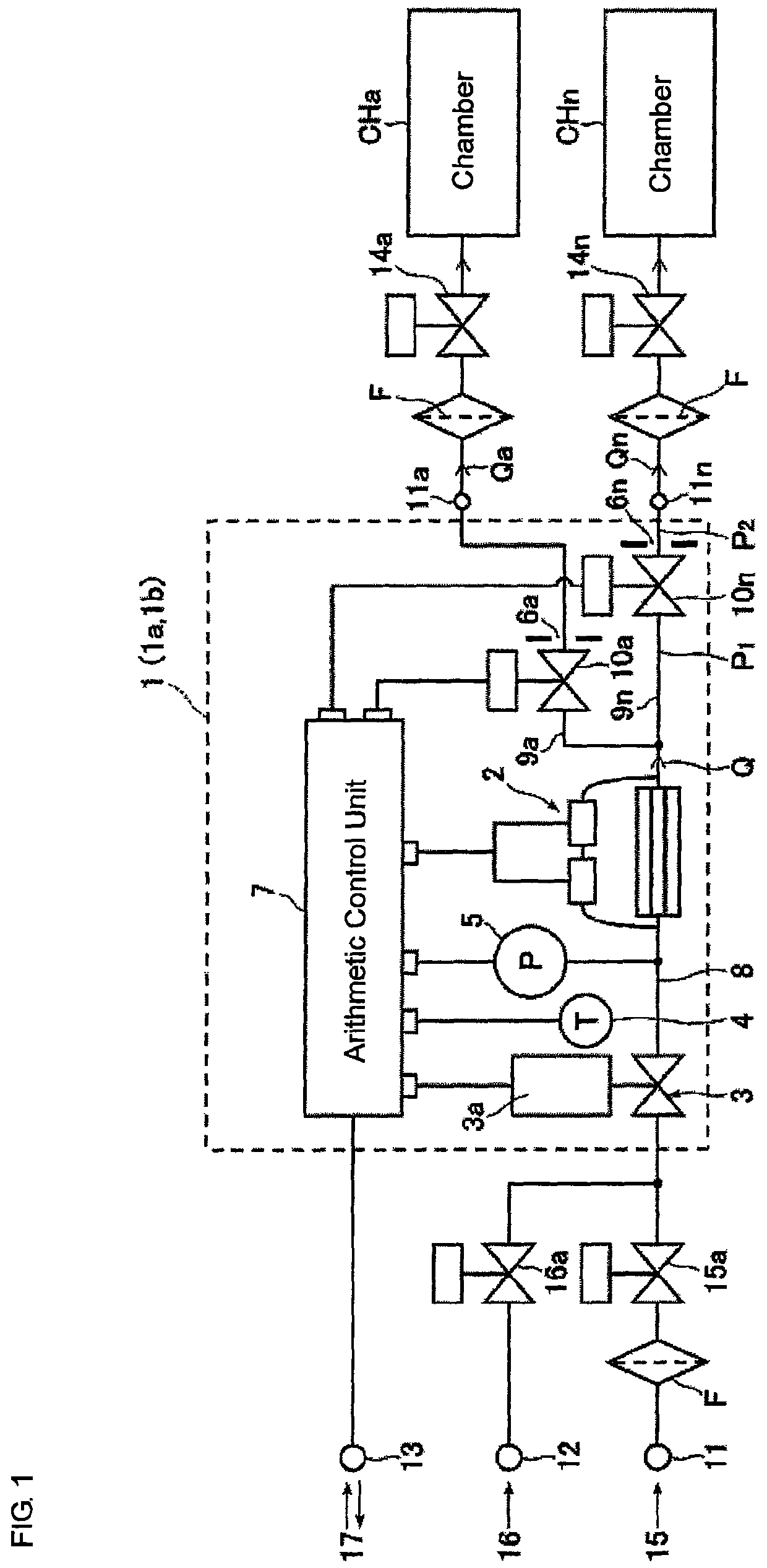
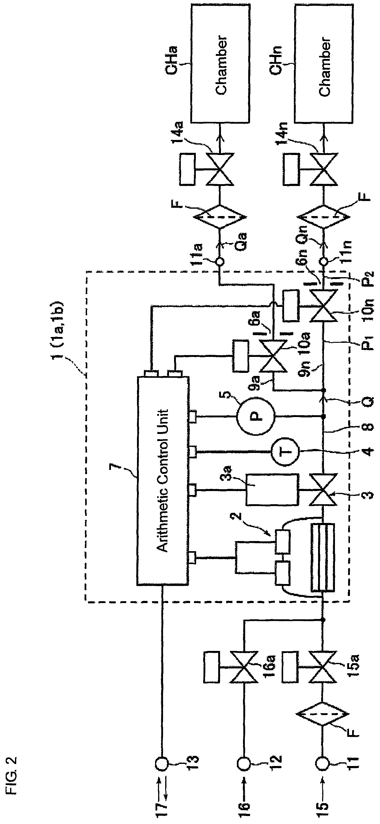
[0042]FIG. 1 is a block diagram according to a first preferred embodiment of a gas divided flow supplying apparatus for semiconductor manufacturing equipment according to the present invention, and this gas divided flow supplying apparatus comprises two portions of a pressure type flow control unit and a thermal type flow control unit.

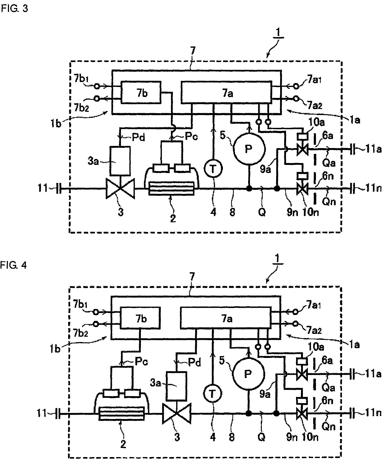
[0043]That is, the gas divided flow supplying apparatus 1 includes a pressure type flow control unit 1a and a thermal type flow control unit 1b. The pressure type flow control unit 1a further includes a control valve 3, a temperature sensor 4, a pressure sensor 5, a plurality of orifices 6a, 6n, a pressure type flow rate arithmetic and control unit 7a forming an arithmetic and control unit 7 and a gas supply main pipe 8, etc., and when gas flows distributed through the orifices 6a, 6n are un...


PUM


Abstract

A gas divided flow supplying apparatus, including a control valve 3, a pressure type flow control unit 1a connected to a process gas inlet 11, a gas supply main pipe 8 connected to the downstream side of control valve 3, a plurality of branched pipe passages 9a, 9n connected in parallel to the downstream side of main pipe 8, opening and closing valves 10a, 10n interposed in the respective branched pipe passages 9a, 9n, orifices 6a, 6n provided on the downstream sides of valves 10a, 10n, a temperature sensor 4 provided near the process gas passage between the control valve 3 and the orifices 6a, 6n, a pressure sensor 5 provided in the process gas passage between the control valve 3 and the orifices 6a, 6n, divided gas flow outlets 11a, 11n provided on the outlet sides of the orifices 6a, 6n, and an arithmetic and control unit 7.

Description

[0001]This is a National Phase application in the United States of International Patent Application No. PCT / JP2013 / 002257 filed Apr. 1, 2013, which claims priority on Japanese Patent Application No. 2012-103857, filed Apr. 27, 2012. The entire disclosures of the above patent applications are hereby incorporated by reference.TECHNICAL FIELD[0002]The present invention relates to an improvement in a gas supplying apparatus for semiconductor manufacturing equipment, and specifically, to a gas divided flow supplying apparatus for semiconductor manufacturing equipment that can accurately divide and supply necessary amounts of a process gas to a plurality of process chambers to perform the same process by using a plurality of orifices joined in parallel as orifices of a pressure type flow control system, and enables to arbitrarily check actual flow rates of the process gas being divided and supplied by organically combining the pressure type flow control system with a thermal type mass flo...

Claims


Application Information

Patent Timeline
Patent Type & Authority Patents(United States)
IPC IPC(8): G05D7/06
CPCG05D7/0641Y10T137/87772G05D7/0664G05D7/06H01L21/02
Inventor NISHINO, KOUJIDOHI, RYOUSUKEHIRATA, KAORUSUGITA, KATSUYUKIIKEDA, NOBUKAZU
Owner FUJIKIN INC
Why Eureka
Try Eureka