Chain tensioner

a chain tensioner and tensioner technology, applied in the direction of belts/chains/gearings, mechanical equipment, belts/chains/gearings, etc., can solve the problems of reducing the adjustment range of each individual tensioner, restricting the retraction of the plunger, and reducing the manufacturing cost. , the effect of preventing the plunger from seizing

Active Publication Date: 2013-10-29
TSUBAKIMOTO CHAIN CO
View PDF11 Cites 0 Cited by
  • Summary
  • Abstract
  • Description
  • Claims
  • Application Information

AI Technical Summary

Benefits of technology

[0010]A general aim of the invention is to address one or more of the aforementioned problems. Accordingly, aspects of the invention include elimination of “flip-flop” noises on engine start-up, providing for improved smoothness in the advancing movement of the plunger, simplification and downsizing of the tensioner structure, prevention of seizing of the plunger by permitting movement of the plunger in the retracting direction when chain tension becomes excessive, reducing excessive noise, and simplifying installation, removal and maintenance of the tensioner.
[0014]The chain tensioner according to the invention has several advantages over conventional chain tensioners. First, because the ratchet mechanism comprises a resilient ring disposed within the plunger-accommodating hole, the tensioner housing can be downsized. Second, the retracting and protruding movement of the plunger can be readily adjusted for each individual tensioner by selecting the inclination angles of the annular circumferential groove in the plunger-accommodating hole and by selecting the inclination angles of the rack teeth of the plunger. Accordingly, it is a simple matter to design the ratchet mechanism to satisfy various conditions of operation, and manufacturing costs are reduced. Third, the resilient ring can be prevented from crossing over the rack tooth tips in the retracting direction on engine start-up, but permitted to cross over the rack tooth tips portion as the resilient ring expands when chain tension becomes excessive during engine operation. Accordingly, it is possible to prevent seizing of the plunger and to reduce the excessive noise, sometimes referred to as a “beat note,” generated when the chain tension becomes excessive. Fourth, the convex shape of the forward surfaces of the rack teeth allows the plunger to protrude smoothly, thereby eliminating the “flip-flop” noise generated on engine start-up.
[0015]In a preferred embodiment, each rack tooth has a cylindrical tip surface having a uniform diameter interposed between its sloping front and rear sides. Accordingly, the pressure acting against the inner peripheral surface of the plunger-accommodating hole is reduced, and smooth advancing and retracting movement of the plunger can be achieved.
[0016]The resilient ring can be a C-ring that can readily expand and contract within the annular circumferential groove. Accordingly, the ratchet structure is simplified. Moreover, the C-ring obviates radially protruding ratchet parts, allowing the tensioner housing to be downsized. In addition, the ring can be selected for the desired resilience so that manufacturing costs can be reduced.
[0017]The resilient ring can also be in the form of an annular ring provided with lever portions extending radially outward therefrom. This embodiment has the advantages of the above-described C-ring. In addition, man operator can easily enlarge and reduce the annular ring manually by manipulation of the lever portions, and thereby more readily install, remove, and maintain the ring.
[0018]The tensioner housing can include a threaded outer circumferential surface, whereby the tensioner can be mounted by engaging its threads with mating threads formed in an opening in a wall of an engine. The utilization of a resilient ring in the ratchet mechanism, and the incorporation of threads on the outside of the tensioner housing allow a significant downsizing of the tensioner as well as simple assembly, installation, and removal for maintenance.

Problems solved by technology

On engine start-up, oil pressure is not yet built up in the oil chamber of the tensioner, and, if the engine has not been operated for a long time, oil in the oil chamber may be depleted.
Until oil pressure is reestablished, the plunger can retract excessively, causing the timing drive to generate a rattling noise.
The prior art ratchet mechanism not only restricts retracting movement of the plunger on engine start-up, but also restricts retraction of the plunger when excessive chain tension occurs during normal engine operation, due to temperature changes and other causes.
In this case, seizing of the plunger can occur, resulting in an increased load on the chain and the generation of excessive noise.
However, as the amount of allowable backlash increases, the amount of rattling noise generated on engine start-up also increases.
Consequently the advancing movement of the plunger depends on the plunger position relative to the ring, the damping response of the tensioner becomes uneven, the plunger does not advance smoothly, and “flip-flop” noises are generated.
The pawl mechanism also increases the complexity of the tension, and makes installation and removal of the tensioner more difficult.
Furthermore, designing the ratchet mechanisms of these prior art chain tensioners so that their characteristics meet operating conditions requires modification of the entire tensioner, thereby increasing manufacturing costs.

Method used


Image

  • Chain tensioner
  • Chain tensioner
  • Chain tensioner

Examples


Embodiment Construction

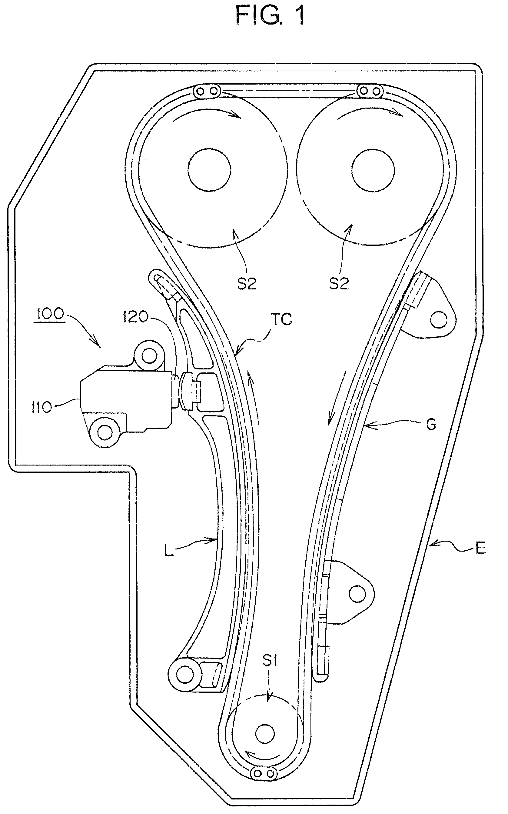
[0042]As shown in FIG. 1, a chain tensioner 100 is used in the timing drive of an engine E. The timing drive comprises an endless chain TC, driven by a crankshaft sprocket S1, and in driving relationship with two camshaft sprockets S1 and S2. A pivoted tensioner lever L, in sliding contact with a span of the chain TC that travels from sprocket S1 to sprocket 22, guides and maintains adequate tension in the chain. The tensioner lever L is pivoted on the engine E and biased into engagement with the chain by a protruding plunger of the chain tensioner 100. A stationary guide G, fixed to the engine E, is in sliding contact with a span of the chain that travels from sprocket S2 toward sprocket S1.

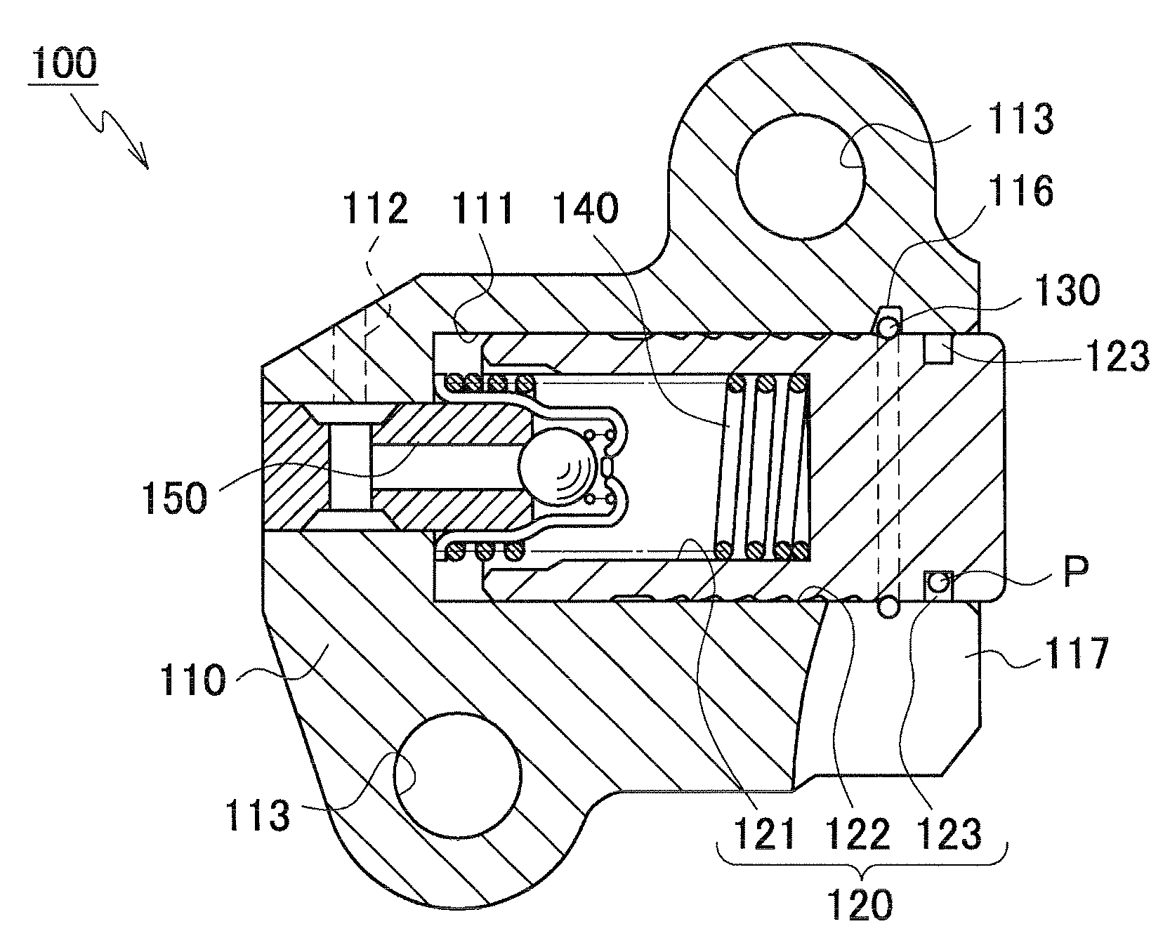
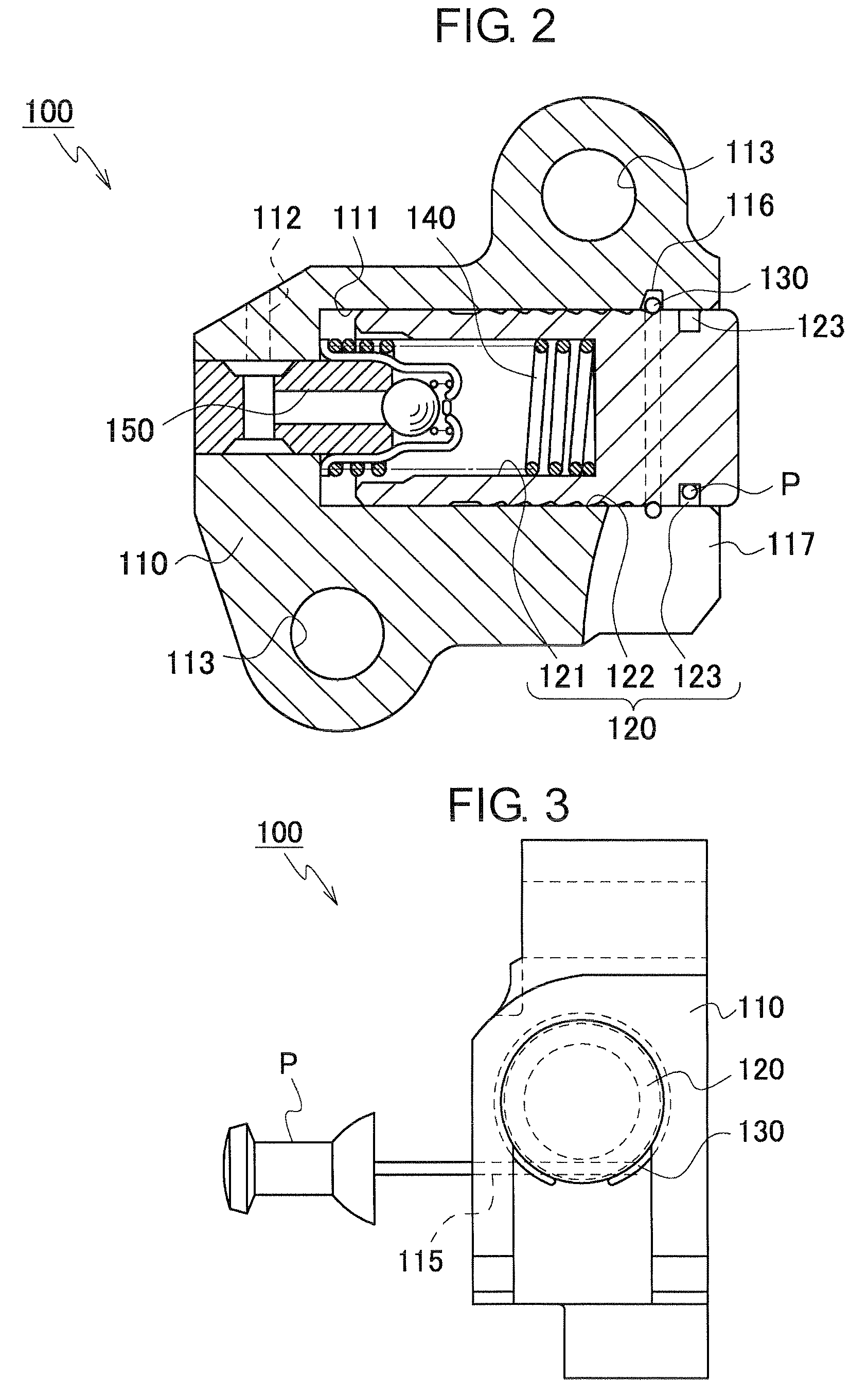
[0043]As shown in FIGS. 2 and 3, the tensioner 100 comprises a housing 110, a hollow cylindrical plunger 120, slidable in and protruding from an opening at the end of a plunger-accommodating hole 111 in the housing. The tensioner also comprises a resilient C-ring 130, a plunger-biasing spring 14...


PUM


Abstract

In a tensioner having a ratchet mechanism composed of annular teeth on a plunger and an expansible resilient ring disposed in a groove formed in the inner peripheral surface of a plunger-accommodating hole in a tensioner housing, the rear surfaces of the annular teeth have a steep slope, and the front surfaces of the annular teeth have a gradual slope with a convex curvature such that the rate of change of the slope decreases proceeding in the direction of retraction of the plunger.

Description

CROSS REFERENCE TO RELATED APPLICATIONS[0001]This application claims priority on the basis of Japanese Patent Application 2010-117705, filed on May 21, 2010. The disclosure of Japanese Patent Application 2010-117705 is incorporated by reference.FIELD OF THE INVENTION[0002]The invention relates to a chain tensioner in which a plunger is slidable in, and protrudes from, a cylindrical plunger-accommodating hole in a tensioner housing, and is biased in the protruding direction so that it can maintain adequate tension in a traveling transmission chain.BACKGROUND OF THE INVENTION[0003]A typical application for a chain tensioner is the maintenance of tension in an automobile engine timing chain. In an engine timing drive, an endless transmission chain, for example, a roller chain, is driven by a crankshaft sprocket and in driving relationship with one or more camshaft sprockets. The chain travels in sliding relationship over a movable chain guide which is urged against the chain by the plu...

Claims


Application Information

Patent Timeline
Patent Type & Authority Patents(United States)
IPC IPC(8): F16H7/08
CPCF16H7/0848F16H2007/0806F16H2007/0812F16H2007/0853F16H2007/0855F16H2007/0859F16H7/08F16H7/18
Inventor HAYAMI, ATSUSHIYOSHIDA, OSAMUKUREMATSU, YUJI
Owner TSUBAKIMOTO CHAIN CO
Why Eureka
Try Eureka