Fluid flow rate control valve, anchor for mover and fuel injection system

a flow rate control valve and flow rate technology, applied in the direction of valve operating means/release devices, machines/engines, etc., can solve the problems of foreign engine noise, uneven wear, and the inability of the mover to slide in a correct manner

Inactive Publication Date: 2006-11-07
BOSCH CORP
View PDF20 Cites 60 Cited by
  • Summary
  • Abstract
  • Description
  • Claims
  • Application Information

AI Technical Summary

Problems solved by technology

Thus, there is such a fear that sliding wear (uneven wear) occurs especially at the contact area of the supporting points, thus making it impossible for the mover to slidingly move in a correct manner.
Here again, there is a fear that uneven wear occurs.
In addition, in case of a common rail system (pressure accumulation type injection system), for example, inferior pressure controlling would occur with a result that foreign engine noises are generated.
Therefore, excessive fuel oil is return...

Method used


Image

  • Fluid flow rate control valve, anchor for mover and fuel injection system
  • Fluid flow rate control valve, anchor for mover and fuel injection system
  • Fluid flow rate control valve, anchor for mover and fuel injection system

Examples


Embodiment Construction

)

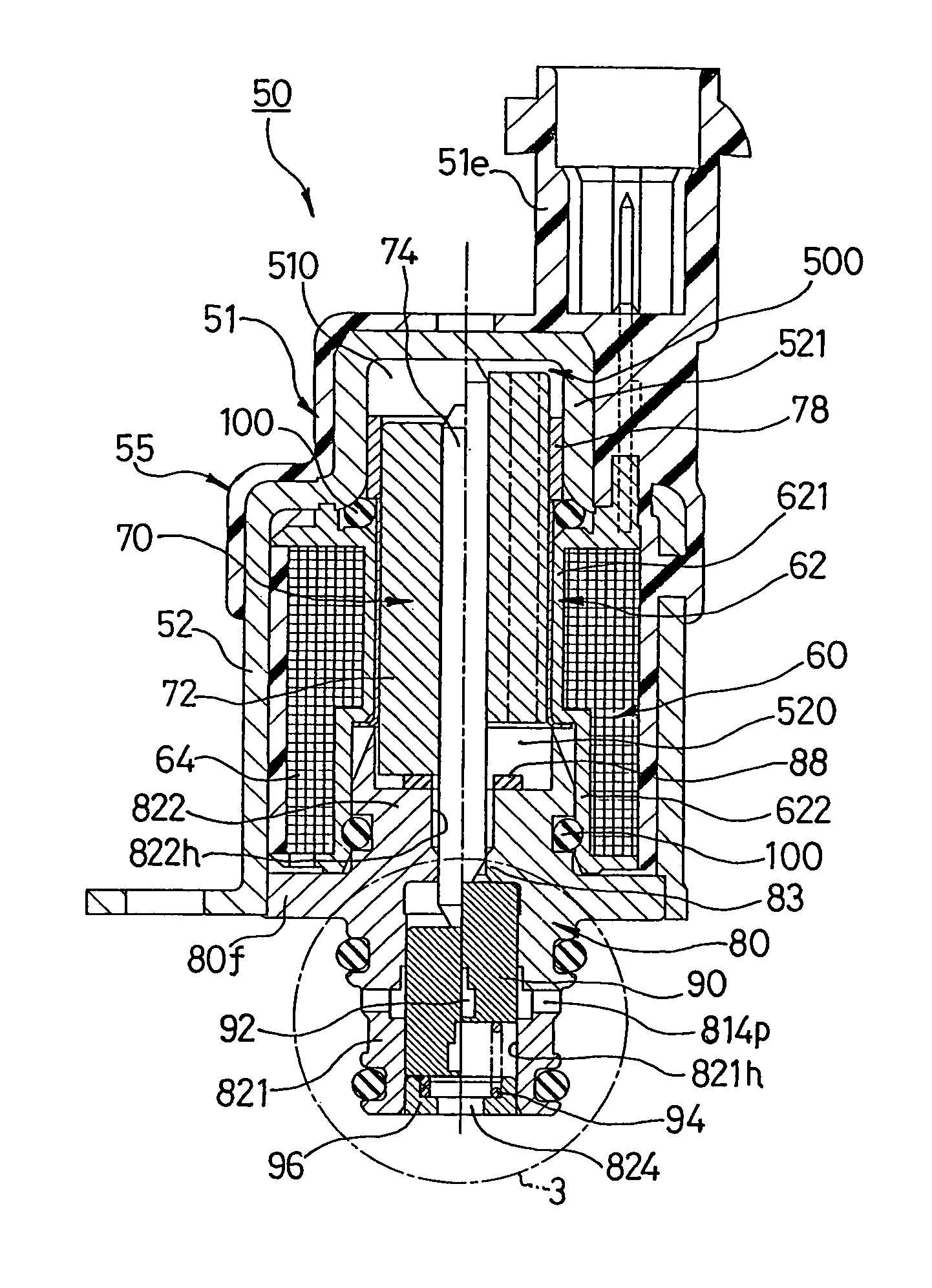
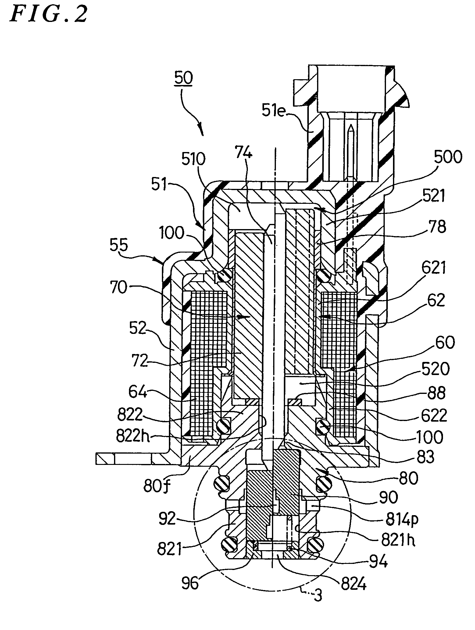
[0027]When the present invention is applied to a flow rate control valve which requires flow rate control characteristics more delicately, the more significant merit can be obtained. From this point of view, the present invention can effectively be applied to an amount control valve for controlling an amount of fuel as fluid to be fed from a low pressure side to a high pressure side in a fuel injection system (diesel engine or gasoline engine) of a vehicle. The illustrated embodiment(s) is examples in which the present invention is applied to an amount control valve in a common rail system of a diesel engine.

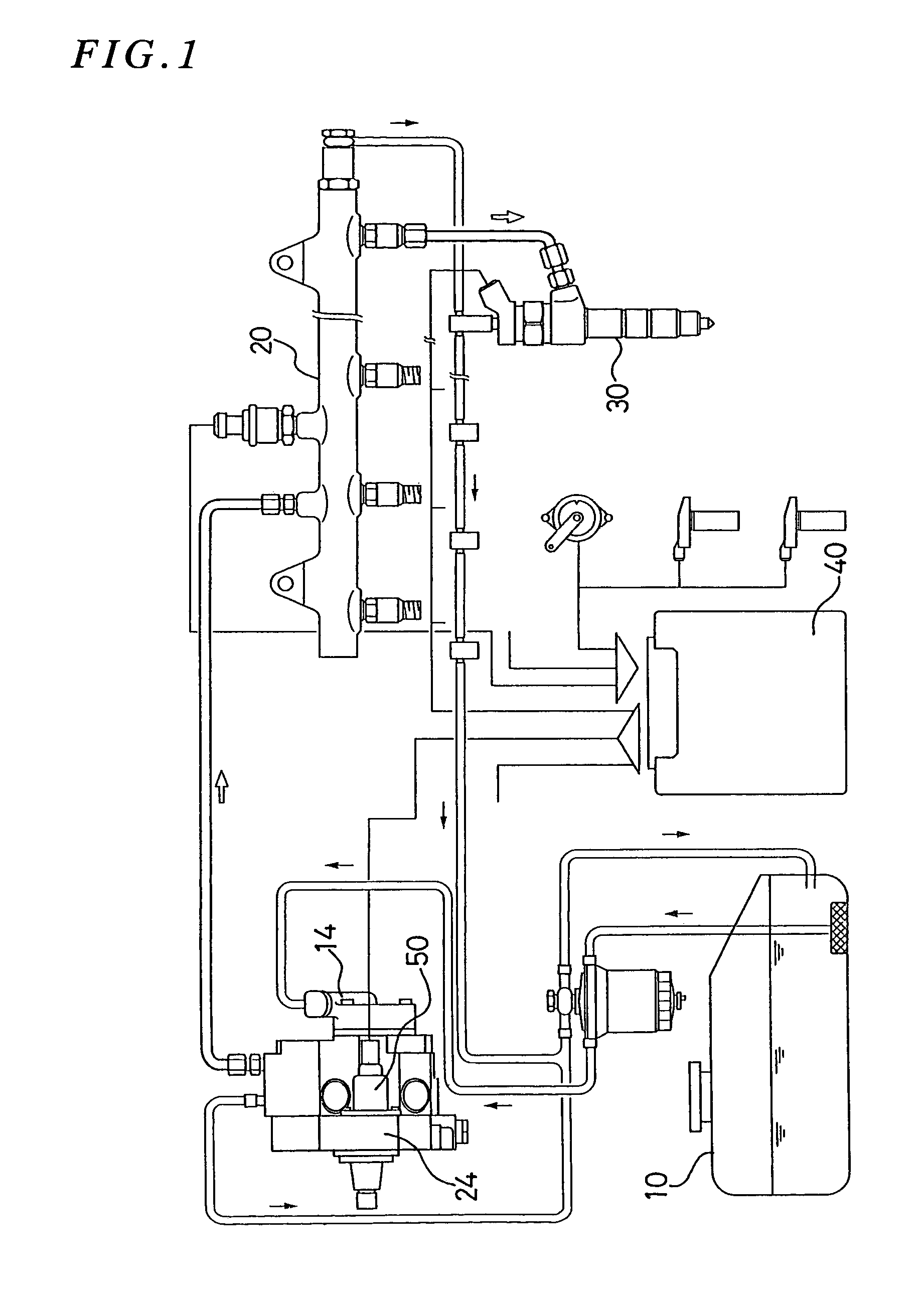
[0028]Referring first to FIG. 1, the outline of a common rail system of a diesel engine and the positional relation of an amount control throttle valve in the system will be described. The common rail system is a system in which fuel oil as fluid is pumped up from a fuel tank 10 and after the fuel oil is boosted to higher pressure, it is accumulated in a common rail 20, and the...


PUM


Abstract

To effectively prevent uneven wear of a moving mover 70 and to stabilize the control characteristics by a valve. Rotation force is exerted to the mover 70 by the fluid flowing from the first chamber to the second chamber, or vice versa, which are formed at the opposite ends of the mover 70. With respect to a flow passageway 110 formed within an anchor 72 and for allowing passage of the fluid therethrough, there are provided a passageway portion 111 which is disposed along the axial direction and another passageway portion 112 which crosses the axial direction. By this, rotation force is generated at the time the fluid passes from the former passageway portion 111 to the latter passageway portion 112 (or vice versa) which crosses the axial direction.

Description

[0001]This application is a 371 of PCT / JP02 / 12365 filed on Nov. 27, 2002 and claims priority benefits of Japanese Patent Application No. 2001-361044 filed Nov. 27, 2001.FIELD OF THE INVENTION[0002]This invention relates to a flow rate control valve for controlling the flow rate of fluid flowing through a valve by controlling opening / closing of the valve under the effect of electromagnetic force. More particularly, it relates to a technique which is suitably used as a flow rate control valve for controlling an amount of fuel used for a vehicle such as a diesel engine or the like.BACKGROUND OF THE INVENTION[0003]In general, an electromagnetic flow rate control valve comprises a circular cylindrical solenoid which generates magnetic field when electric current is supplied thereto and a mover which moves in the axial direction under the effect of electromagnetic force when the solenoid is magnetized. The mover is located in an internal space of a housing and normally, it has a circular ...

Claims


Application Information

Patent Timeline
IPC IPC(8): F02M59/36F02M37/00F02M37/04F02M59/34F02M59/46F02M63/02F16K29/00F16K31/06
CPCF02M59/34F02M59/366F02M63/0017F02M63/004F02M63/0078F02M63/0225F16K29/00F16K31/0613F16K31/0624F16K31/0655
Inventor ICHINOSE, TAKESHIWESSNER, JOCHENKEIMER, HERMANNKLINK, WOLFGANGMIEHLE, TILMAN
Owner BOSCH CORP
Why Eureka
Try Eureka