Method for producing battery electrode

a battery electrode and electrode active material technology, applied in the manufacturing process of electrodes, cell components, electrochemical generators, etc., can solve the problems of battery capacity decline, difference in potential in the electrode plane, and structural disorder caused by expansion and contraction of negative electrode active materials, etc., to improve the flatness of the active material layer of the electrode.

Active Publication Date: 2020-10-01
NISSAN MOTOR CO LTD
View PDF0 Cites 0 Cited by
  • Summary
  • Abstract
  • Description
  • Claims
  • Application Information

AI Technical Summary

Benefits of technology

[0006]In this regard, an object of the present invention is to provide a means capable of improving the flatness of a surface of a

Problems solved by technology

Therefore, in a negative electrode active material layer containing silicon-containing negative electrode active material, there is a concern that the structural disorder caused by expansion and contraction of the negative electrode active material occurs as charge-discharge cycle proceeds.
When the flatness of the surface of the active material layer is low, the distance between electrodes (the di

Method used


Image

  • Method for producing battery electrode
  • Method for producing battery electrode
  • Method for producing battery electrode

Examples


example 1

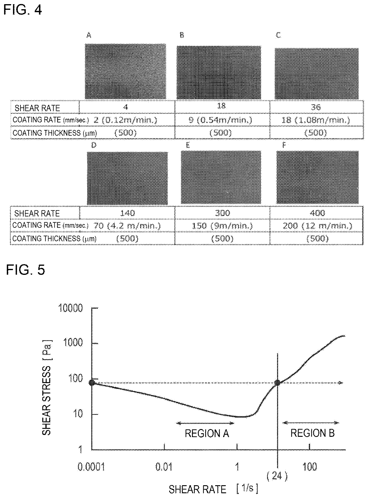
[0230]A coating film (negative electrode active material layer) was formed on the surface of the current collector by the same method as in Comparative Example 1 described above, except that the coating rate was set to 9 [mm / s]. Incidentally, since the coating rate in this Example was 9 [mm / s], the shear rate was 9 [mm / s] / 0.5 [mm]=18 [l / s], and the shear stress corresponding to this was a value larger than the yield stress of the used negative electrode active material slurry.

example 2

[0231]A coating film (negative electrode active material layer) was formed on the surface of the current collector by the same method as in Comparative Example 1 described above, except that the coating rate was set to 18 [mm / s]. Incidentally, since the coating rate in this Example was 18 [mm / s], the shear rate was 18 [mm / s] / 0.5 [mm]=36 [l / s], and the shear stress corresponding to this was a value larger than the yield stress of the used negative electrode active material slurry.

example 3

[0232]A coating film (negative electrode active material layer) was formed on the surface of the current collector by the same method as in Comparative Example 1 described above, except that the coating rate was set to 70 [mm / s]. Incidentally, since the coating rate in this Example was 70 [mm / s], the shear rate was 70 [mm / s] / 0.5 [mm]=140 [l / s], and the shear stress corresponding to this was a value larger than the yield stress of the used negative electrode active material slurry.


PUM


Abstract

Provided is a means capable of improving the flatness of a surface of an electrode active material layer in which an electrode active material slurry without assuming addition of a binder.
Upon producing a battery electrode which has a current collector and an electrode active material layer disposed on a surface of the current collector and containing an electrode active material, in a coating step of coating an electrode active material slurry in which the electrode active material is dispersed in a solvent on the surface of the current collector to form the electrode active material layer, an electrode active material slurry which has flow characteristics that a region A in which a shear stress is not increased according to an increase in shear rate is present and a region B in which a shear stress is increased and an increase rate thereof is decreased according to an increase in shear rate is present in a region having a shear rate larger than that of the region A, in a shear rate (horizontal axis)-shear stress (vertical axis) curve of the electrode active material slurry, is used as the electrode active material slurry, and, coating of the electrode active material slurry is performed at a coating rate at which the shear rate at the time of coating is a value in which a shear stress equal to or more than a yield stress of the electrode active material slurry is applied in the coating step.

Description

TECHNICAL FIELD[0001]The present invention relates to a method for producing a battery electrode.BACKGROUND ART[0002]In recent years, the use of various electric vehicles has been promoted with the expectation of solving environmental and energy issues. Secondary batteries are being developed intensively as a vehicle-mounted power source such as a motor drive power source, which holds the key to the widespread use of these electric vehicles. In the electric vehicles, in order to lengthen a cruising distance per one charge, secondary batteries having a higher energy density are desired.[0003]As a technique for improving the energy density of a non-aqueous electrolyte secondary battery such as a lithium ion secondary battery, searching of an electrode active material having a higher capacity has been intensively conducted. For example, a silicon-containing negative electrode active material occludes / releases 3.75 mol of lithium ions per 1 mol as in the following Reaction Formula (A) i...

Claims


Application Information

Patent Timeline
IPC IPC(8): H01M4/04H01M4/36H01M4/62H01M10/0525H01M4/139
CPCH01M4/0404H01M4/624H01M4/366H01M10/0525H01M4/62Y02E60/10H01M2004/027H01M2004/028
Inventor TOYOSHIMA, KENICHIKOSEMURA, TOORUYOKOYAMA, YUICHIROEMORI, YUSUKE
Owner NISSAN MOTOR CO LTD
Why Eureka
Try Eureka