Positive crankcase ventilation valve assembly

Active Publication Date: 2006-11-07
FCA US
View PDF7 Cites 11 Cited by
  • Summary
  • Abstract
  • Description
  • Claims
  • Application Information

AI Technical Summary

Benefits of technology

[0005]Accordingly, an improved positive crankcase ventilation valve assembly is provided. In accordance with one aspect of the present invention, the positive crankcase ventilation valve assembly includes a housing having a first end and a second end and a flow path therebetween. A positive crankcase ventilation valve is provided and positioned relative to the housi

Problems solved by technology

Existing positive crankcase ventilation valves have been known to freeze in a closed position in cold climates thus preventing ventilation of crankcase gases until the valve un-freezes.
Positive crankcase ventilation valves are also known to experience oil contamination in the valve itself as well as in the intake manifold and a hose that routes the gases from the valve to the intake manifold.
One result of this arrangement is that by

Method used


Image

  • Positive crankcase ventilation valve assembly
  • Positive crankcase ventilation valve assembly
  • Positive crankcase ventilation valve assembly

Examples


Embodiment Construction

)

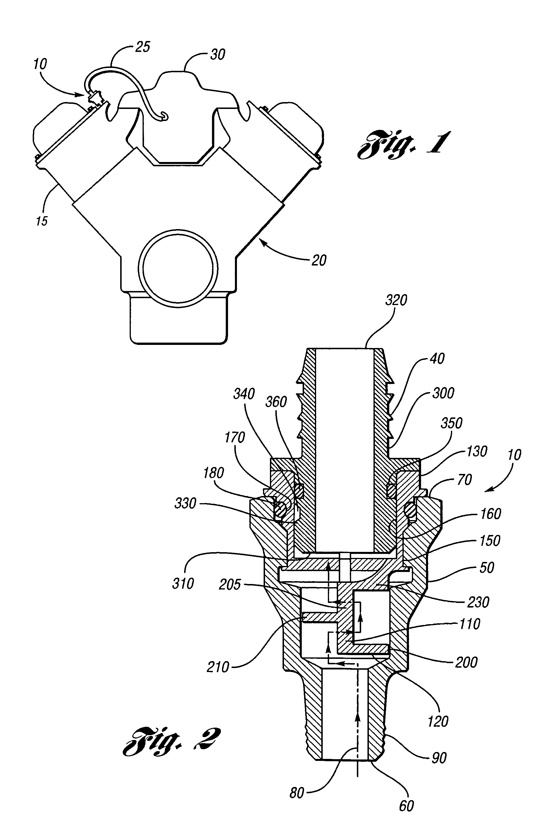
[0010]In the following description, several well-known features of an internal combustion engine are not shown or described so as not to obscure the present invention. Referring now to the drawings, FIGS. 1–3 illustrate an exemplary embodiment of a positive crankcase ventilation valve assembly 10 affixed to a cylinder head 15 of an engine assembly 20 whereby crankcase gases are routed from the positive crankcase valve assembly 10 via hose 25 to an intake manifold 30.

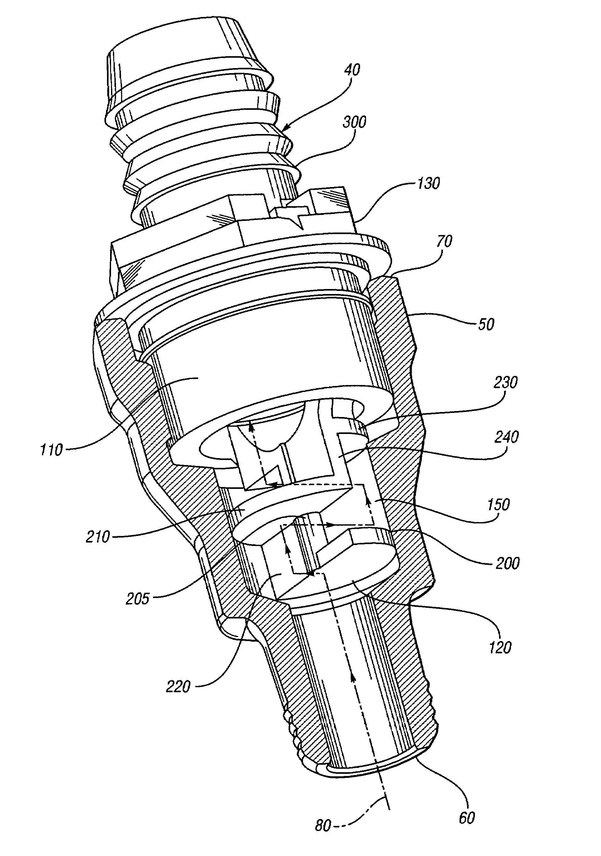
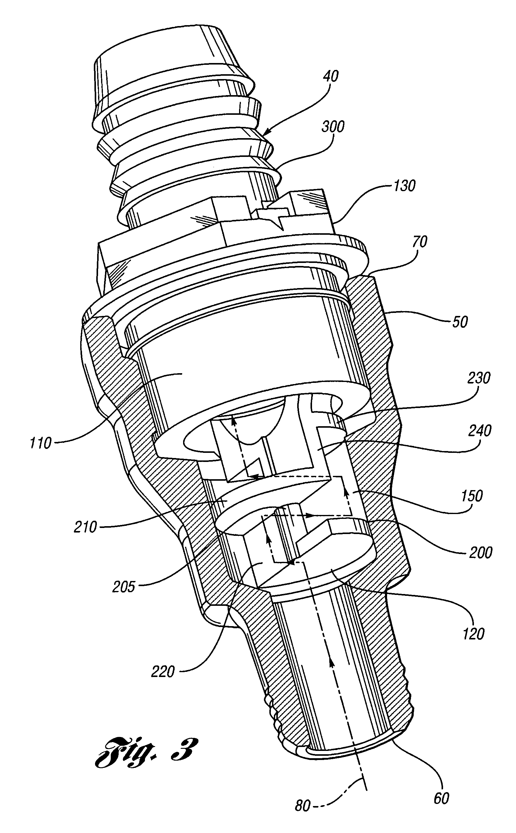
[0011]The positive crankcase ventilation valve assembly 10 includes a positive crankcase ventilation valve 40 and a housing 50 that provides structure and function for the assembly. Housing 50 is preferably constructed or molded from a plastic material such as a thermoset or thermoplastic material. Housing 50 has a first end 60 and a second end 70 with a general flow path 80 therebetween. Housing first end 60 is arranged to be fixedly attached to an engine in a conventional manner such as using external threads 90 and b...


PUM


Abstract

A positive crankcase ventilation valve assembly is provided. The positive crankcase ventilation valve assembly includes a housing having a first end and a second end and a flow path therebetween. A positive crankcase ventilation valve is provided and positioned relative to the housing first end and in fluid communication with the housing flow path. A baffle is provided and positioned in the housing and in fluid communication with the housing flow path, wherein the baffle is arranged to allow crankcase gases to flow through the baffle and into the positive crankcase ventilation valve while preventing engine oil from traveling beyond the baffle.

Description

FIELD OF INVENTION[0001]The present invention relates generally to crankcase ventilation valves, and, more particularly, to an improved positive crankcase ventilation valve assembly.BACKGROUND OF INVENTION[0002]Crankcase ventilation valves are generally utilized to vent crankcase gases from an internal combustion engine and route the gases to an intake manifold. Positive crankcase ventilation valves typically meter a flow of gases from the crankcase to the intake manifold. Existing positive crankcase ventilation valves have been known to freeze in a closed position in cold climates thus preventing ventilation of crankcase gases until the valve un-freezes. Positive crankcase ventilation valves are also known to experience oil contamination in the valve itself as well as in the intake manifold and a hose that routes the gases from the valve to the intake manifold. To counter this situation positive crankcase ventilation valves have been known to be attached to a top of an engine cylin...

Claims


Application Information

Patent Timeline
IPC IPC(8): F01M13/04
CPCF01M13/0011
Inventor LINDBERG, MICHAEL PROSSMILLER, SCOTT L
Owner FCA US
Why Eureka
Try Eureka