Digital thermal transfer printer

a digital thermal transfer printer and thermal transfer technology, applied in printing, typewriters, instruments, etc., can solve the problems of not being able not being able to describe various colorful images, and spending too much time and expense to prepare a sample of print film, etc., to achieve fast and rapid heating of textile materials, and maximize work efficiency

Inactive Publication Date: 2006-11-07
LEE IN OK
View PDF4 Cites 5 Cited by
  • Summary
  • Abstract
  • Description
  • Claims
  • Application Information

AI Technical Summary

Benefits of technology

[0013]To overcome the above described problems, preferred embodiments of the present invention provide a digital thermal transfer printer comprising not only several heaters drying sequentially transfer ink printed to textile materials, but also a thermal transfer moving horizontally and ejecting hot winds of 180˜600° C. to heat the transfer ink directly to have the production speed of general direct printers to maximize work efficiency, to embody more clear colors of the transfer ink due to the very fast and rapid heating to the textile materials, and eventually to give more trusts to customers.

Problems solved by technology

However, the thermal transfer printing method described in the above statements is used to manufacture a banner or a flag in general, and is not suitable to describe various colorful images.
Therefore, it is troublesome works, and in more, spends too much time and expenses to prepare a sample of the print film.
Therefore, the print film is hardly prepared because of the problems of time and expenses.
However, the direct printing method utilizing the digital printer should adopt an exclusive paper manufactured specially, and does not apply to general textile materials.
In other words, the drying temperature using hot winds at the digital printer is about 60° C., manufacturing efficiency is extremely low so that it takes too much time to dry completely the transfer ink printed to the exclusive paper.
Therefore, the direct printing method makes merchantability of the product low, and does not provide satisfaction to customers.

Method used


Image

  • Digital thermal transfer printer
  • Digital thermal transfer printer
  • Digital thermal transfer printer

Examples


Embodiment Construction

[0022]Reference will now be made in detail to preferred embodiments of the present invention, example of which is illustrated in the accompanying drawings.

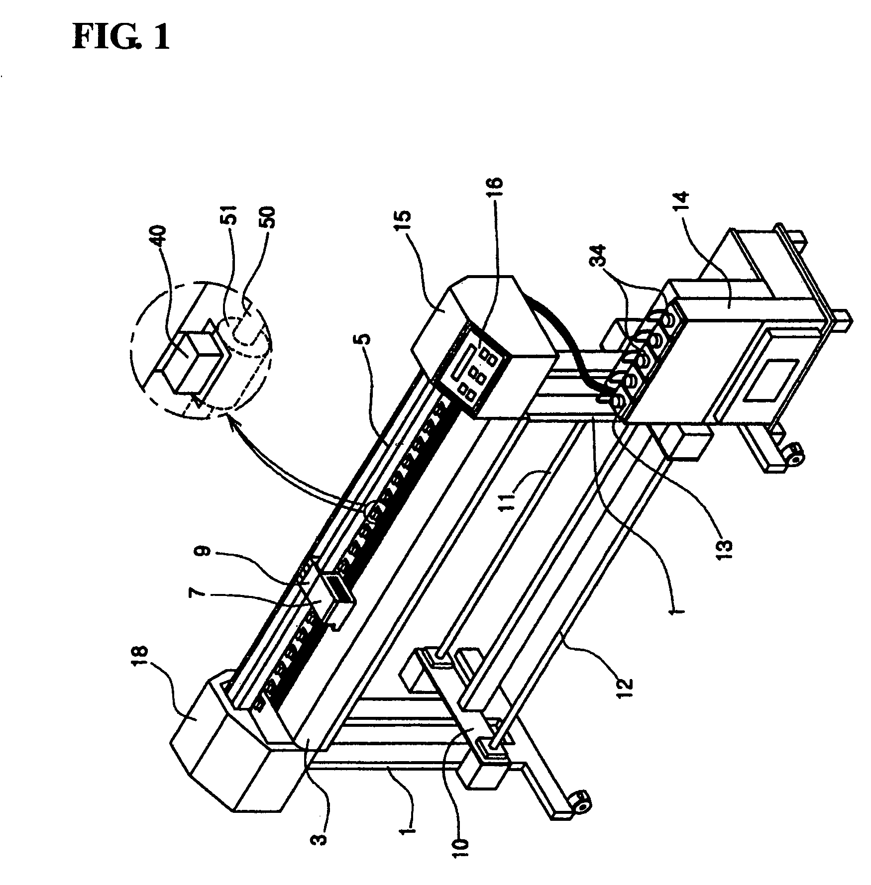
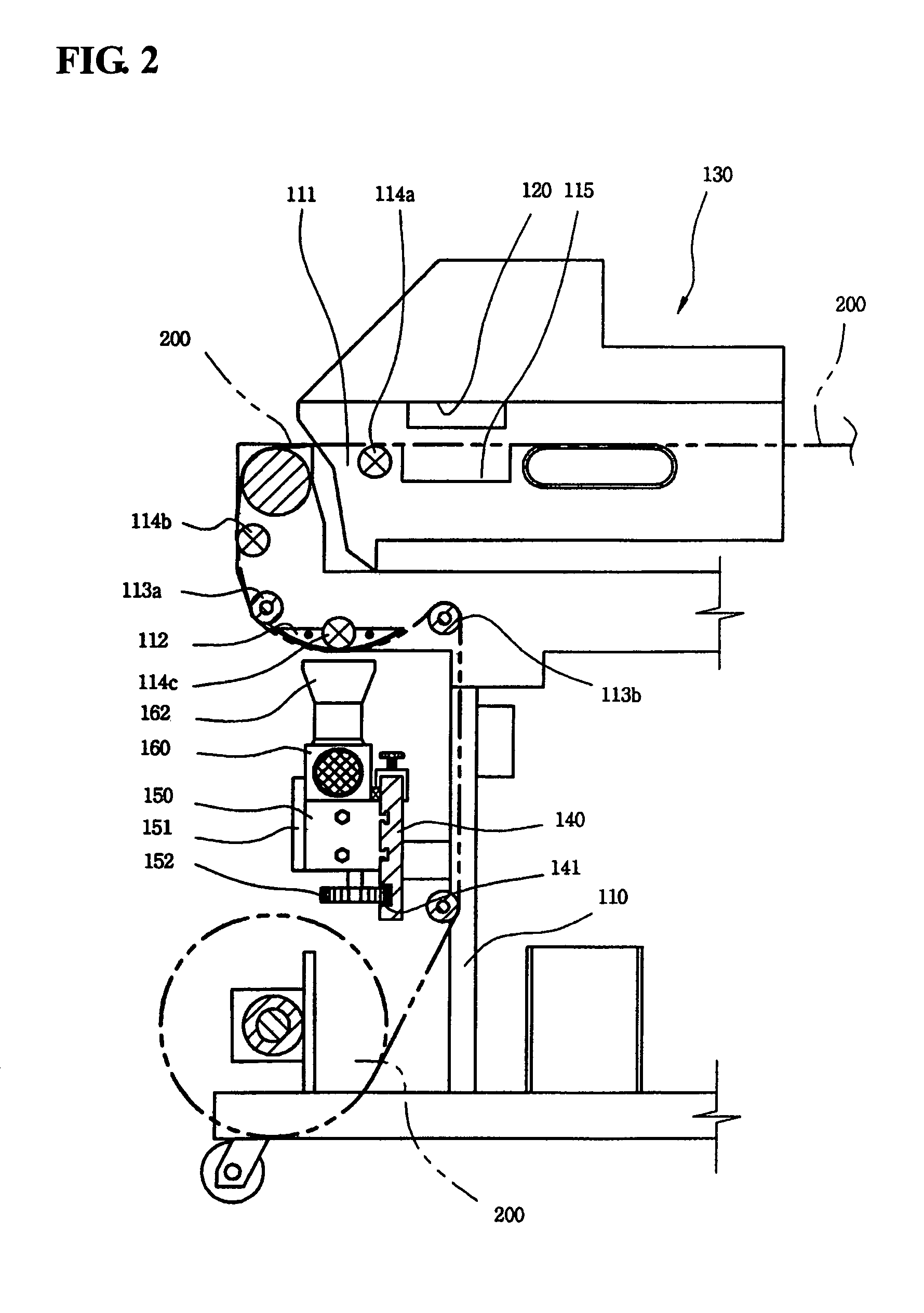
[0023]FIG. 2 is a side view, and FIG. 3 is a front view of a digital thermal transfer printer of the present invention.

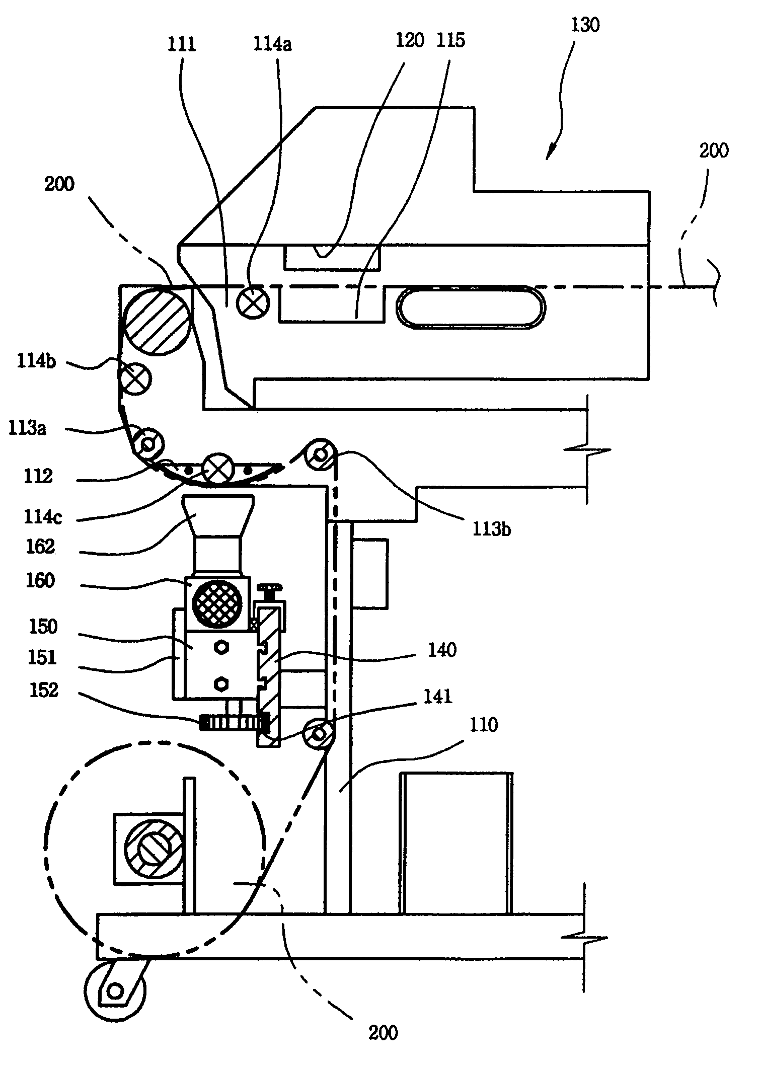
[0024]The digital thermal transfer printer of the present invention comprises a supporter 110 with a predetermined height, a transfer zone 120 including a transfer roller (not shown) connected with a power transfer (not shown) on a base 111 placed under a transfer object 200 such as textile materials to make the transfer object 200 flat, and a main body 130 including a head 131 moving horizontally at the top of the base 111 to print transfer data such as designs to the transfer object by transfer ink ejected from ink cartridge.

[0025]In more, the one surface of the printed transfer object 200 is continuously contacted with a surface guide 112 formed in the bottom of the base 111. Additionally, guiding rollers 113a ...


PUM


Abstract

The present invention discloses a digital thermal transfer printer comprising not only several heaters drying sequentially transfer ink printed to textile materials, but also a thermal transfer moving horizontally and ejecting hot winds of 180˜600° C. to heat the transfer ink directly to have the production speed of general direct printers to maximize work efficiency, to embody more clear colors of the transfer ink due to the very fast and rapid heating to the textile materials, and eventually to give more trusts to customers.

Description

BACKGROUND OF THE INVENTION[0001]1. Field of the Invention[0002]The present invention relates to a digital thermal transfer printer, and more particularly, to the digital thermal transfer printer comprising not only several heaters drying sequentially transfer ink printed to textile materials, but also a thermal transfer moving horizontally and ejecting hot winds of 180˜600° C. to heat the transfer ink directly to have the production speed of general direct printers to maximize work efficiency, to embody more clear colors of the transfer ink due to the very fast and rapid heating to the textile materials, and eventually to give more trusts to customers.[0003]2. Description of the Related Art[0004]Recently, development of various technologies makes industry, especially industrial products, highly advanced and more competitive than ever. As a result, advertisement or design of the industrial products becomes more important factor of the product market shares. Sequentially, to get bett...

Claims


Application Information

Patent Timeline
Patent Type & Authority Patents(United States)
IPC IPC(8): B41J2/315B41J2/01B41J3/407B41J11/00
CPCB41J3/4078B41J11/002B41J11/00216B41J11/0022B41J2/315
Inventor LEE, KILHUN
Owner LEE IN OK
Why Eureka
Try Eureka