Guide apparatus for use in making a hardcover book

a guide apparatus and hardcover technology, applied in the field of book binding, can solve the problems of relatively complex positioning apparatus and user having little training, and is likely to have some difficulty in carrying out the binding process

Active Publication Date: 2006-11-14
POWIS PARKER INC
View PDF61 Cites 14 Cited by
  • Summary
  • Abstract
  • Description
  • Claims
  • Application Information

AI Technical Summary

Benefits of technology

[0010]In use, a cover assembly is positioned on the book receiving surface with edges of the cover assembly engaging the first and second lower cover stops along the orthogonal reference lines. A bound stack is then positioned on the cover assembly, with two orthogonal edges of the stack engaging the respective stack engaging surfaces of the first and second book stops. This

Problems solved by technology

Unfortunately, the positioning apparatus is relatively complex and includes, for example, a mirror to assist in

Method used


Image

  • Guide apparatus for use in making a hardcover book
  • Guide apparatus for use in making a hardcover book
  • Guide apparatus for use in making a hardcover book

Examples


first embodiment

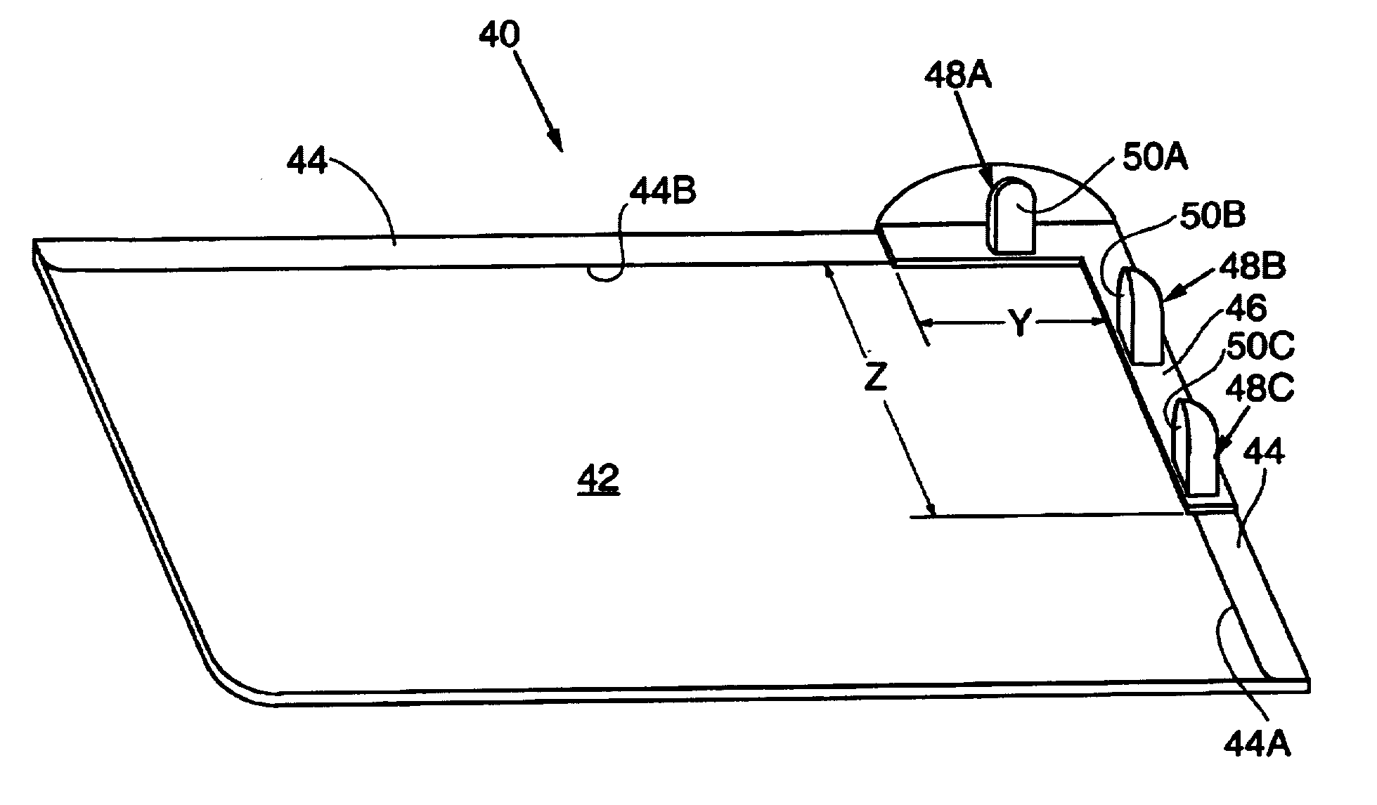
[0039]Referring now to FIGS. 6 and 7, a first embodiment guide apparatus 40 is disclosed for use in carrying out the binding process. The guide apparatus includes a flat base member having a receiving surface 42 that is somewhat larger that the largest book to be bound when the book is in the open position. A stop member 44 having two orthogonal segments is supported on the upper surfaced 42 of the base member and extends around two adjacent sides of the base member. A ledge member 46, also having two orthogonal segments, is supported above the stop member 44 and, as can be in FIG. 7, have outer edges 46A which extend past the edge 44A of the stop member a small distance X, with the overhang being typically 0.16 inches. The height of the ledge member above the support surface is great enough to accommodate the thickness of the cover sections 18A and 18B of the cover assembly 18. The ledge member 46 extends along stop member 44 in one direction a distance Y (FIG. 6) which is somewhat...

second embodiment

[0054]In order to further assure accurate positioning of the hardcover assembly 18 on the bound stack 10, the second embodiment guide apparatus 60 can further include a cover clamp mechanism 80 which grips the hard cover section 18B and reliably secures the hard cover assembly 18 to the guide apparatus. Referring primarily to FIGS. 14, 15A and 15B, the cover clamp mechanism 80 is preferably an integral part of the elongated vertical cover stop 64. (Note that FIG. 14 does not show some of the structure of the guide apparatus not related to the clamp mechanism, including the spiral cylinders 72A / 72B and the slide member 76. Further, FIG. 12 does not show the clamp mechanism.) As can best be seen in FIGS. 15A and 15B, the cover clamp mechanism 80 includes a cantilevered spring metal contact member 82 secured to the underside of a base member 80B by way of screw 84. Base member 80B is preferably an integral part of vertical cover stop 64. Contact member 82 is disposed in a recess (not s...


PUM


Abstract

A guide apparatus for applying a cover to a bound stack of sheets, including a base unit which defines a book receiving surface and a first alignment member having a lower cover stop disposed along a reference line, and a first upper cover stop also disposed along the first reference line. A first book stop is included defining a stack engaging surface which is positioned intermediate the cover engaging surfaces of the first upper and lower cover stops and with said stack engaging surface extending a distance past said first reference line towards the book receiving surface. The first upper and lower cover stops are positioned to engage top and bottom cover sections of the cover, with the stack engaging surface being positioned to contact the edge of the stack so as to precisely align the stack with respect to the top and bottom cover sections in one direction. A second alignment member includes elements similar to that of the first alignment member so as to precisely the align the stack with respect to the top and bottom cover sections long a second reference line normal to the first reference line.

Description

CROSS-REFERENCE TO RELATED APPLICATIONS[0001]The present application is a Continuation-In-Part application of Ser. No. 10 / 262,721 filed on Oct. 2, 2002 now abandoned and entitled Method of Making A Hardcover Book and Hardcover Apparatus.BACKGROUND OF THE INVENTION[0002]1. Field of the Invention[0003]The present invention relates generally to the field of bookbinding and, in particular, to a guide apparatus for use in making a hardcover book.[0004]2. Description of Related Art[0005]Binding systems for binding stacks of sheets into a book using desktop equipment have increased in popularity. One popular system uses a binder strip having and adhesive surface, such as disclosed in U.S. Pat. No. 4,496,617. The binder strip is typically applied to a stack of sheets to be bound using a desktop binding machine such as disclosed in U.S. Pat. No. 5,052,873. The binding machine carries out the binding operation by suitably positioning the binder strip relative to the stack to be bound and appl...

Claims


Application Information

Patent Timeline
IPC IPC(8): B42C11/02B42C11/04B42D1/06
CPCB42C11/04
Inventor PARKER, KEVIN P.STEINER, EVELYNKASSOM, WAYNE
Owner POWIS PARKER INC
Why Eureka
Try Eureka