Shoulder brace

a shoulder brace and shoulder technology, applied in the field of orthopaedic braces, can solve the problems of increasing the likelihood of anterior dislocation and even greater chances of anterior dislocation, and achieve the effect of increasing the pressure on the shoulder

Inactive Publication Date: 2006-11-14
FOUNTAINHEAD
View PDF16 Cites 11 Cited by
  • Summary
  • Abstract
  • Description
  • Claims
  • Application Information

AI Technical Summary

Benefits of technology

[0012]It is therefore desirable and an object of the present invention to provide a shoulder brace that provides strong posterior, anterior and / or medial pressure to the shoulder joint of a patient wearing the shoulder strap while not excessively inhibiting motion of the arm. Movement of a patient's shoulder can be broken down into safe zones and danger zones. When a patient moves their arm so that their elbow is above the shoulder joint when the patient is in a standing position, or when the elbow is behind the plane passing between the front and rear side of the body, or when the arm is in excessive external rotation, movements into any such areas would be into a danger zone where the likelihood of an anterior dislocation greatly increases. Furthermore, if such a movement occurs during an athletic activity, where other forces and stresses are exerted upon the shoulder joint, the chances of an anterior dislocation are even greater.
[0013]It is a further object of the present invention to provide a shoulder brace that provides anterior and posterior compression of the shoulder joint when the arm of the patient is moved into a danger zone.
[0014]It is a further object of the present invention to provide a shoulder brace that is less intrusive than that of the braces used in the prior art, causing less interference with a patient's movements and allowing greater range of motion.
[0015]It is yet another object of the present invention to provide a shoulder brace that can provide anterior and posterior compression of a shoulder joint without inhibiting motion of the patient's arm in the upward direction.
[0017]In one embodiment of the present invention, the shoulder brace includes a shoulder member mountable to a shoulder of a patient's arm with an open portion forming substantially rigid first and second arms and a positioning device configured to vary the spacing of the first and second arms according to the position of the patient's arm. By constructing the shoulder brace as such, the present invention avoids undue restriction of movement of the user's arm while efficiently transforming the energy directed into the shoulder brace by the movement of the user's arm into a pressure to the user's shoulder.
[0019]According to another embodiment of the present invention, the shoulder brace includes a first mounting member mountable to a user's pectoral area, a second mounting member mountable to a user's upper arm, and a connecting member connected to the first mounting member at a first end, and connected to the second mounting member at a second end. Additionally, a positioning device is configured to increase a pressure to the user's shoulder according to the movement of the user's arm. By constructing the shoulder brace as such, the shoulder brace efficiently communicates movements of the user's upper arm to the shoulder brace to thereby effect the pressure directed to the shoulder joint.

Problems solved by technology

When a patient moves their arm so that their elbow is above the shoulder joint when the patient is in a standing position, or when the elbow is behind the plane passing between the front and rear side of the body, or when the arm is in excessive external rotation, movements into any such areas would be into a danger zone where the likelihood of an anterior dislocation greatly increases.
Furthermore, if such a movement occurs during an athletic activity, where other forces and stresses are exerted upon the shoulder joint, the chances of an anterior dislocation are even greater.

Method used


Image

  • Shoulder brace
  • Shoulder brace
  • Shoulder brace

Examples


Embodiment Construction

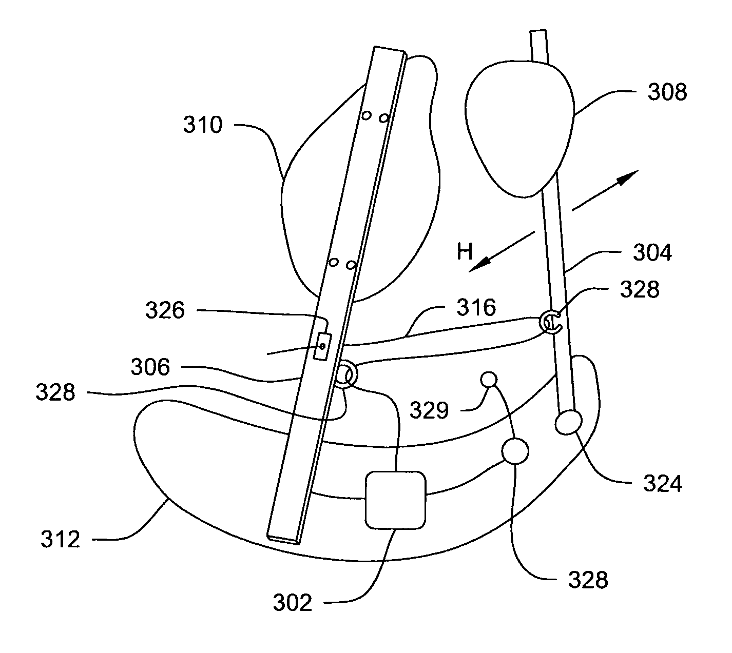
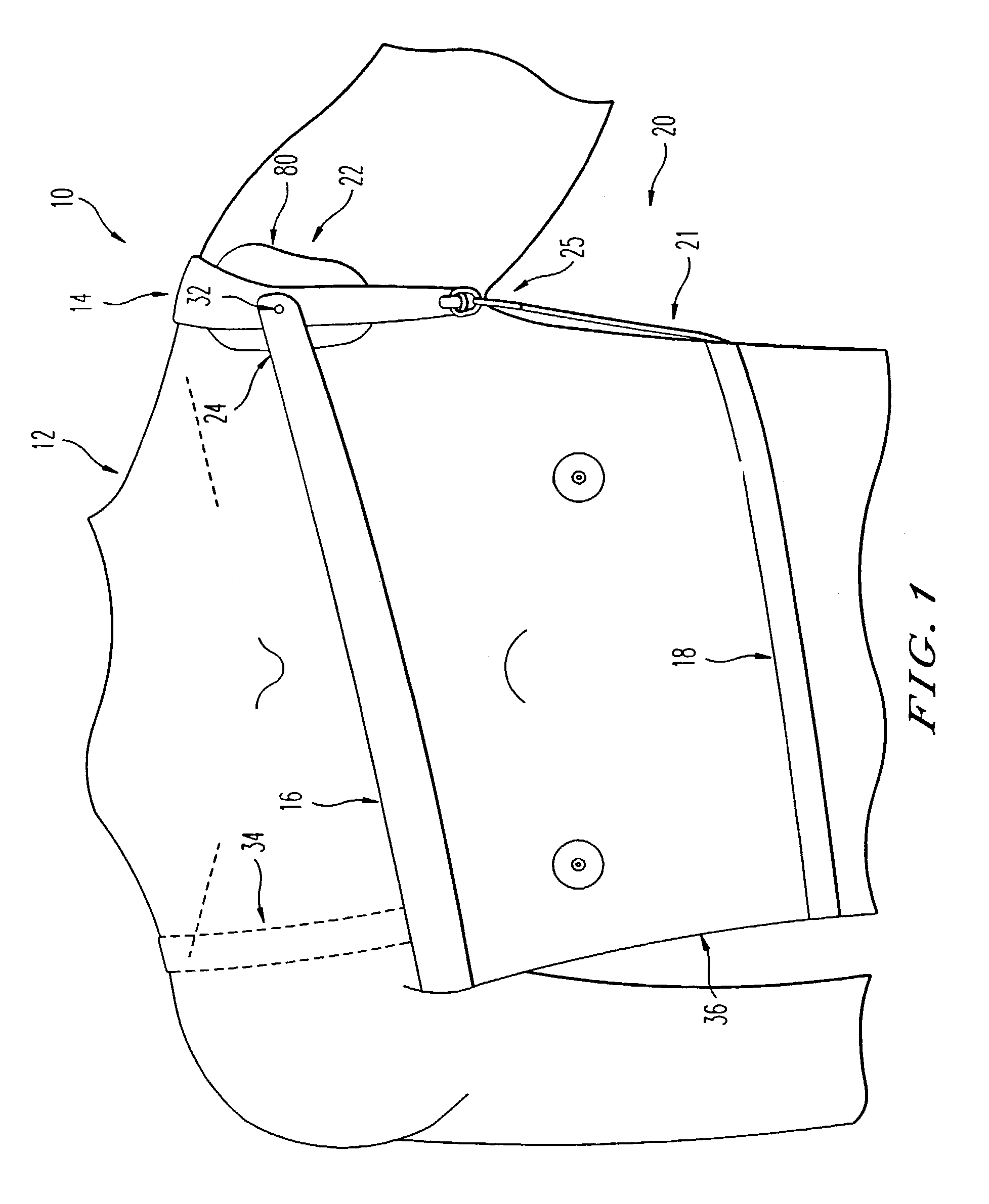
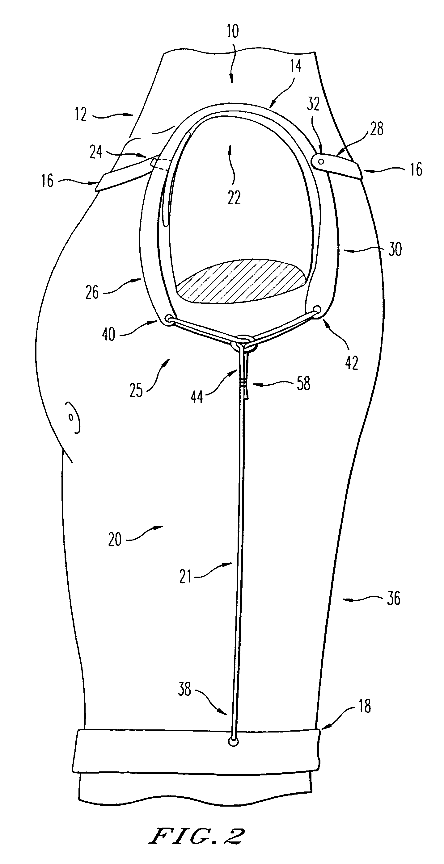
[0052]Referring now to the nonlimiting example of the drawings, wherein like reference numerals designate identical or corresponding parts throughout the several views, and more particularly to FIGS. 1 through 4, thereof, a shoulder strap 10 being worn by a patient 12 is generally shown. Shoulder brace 10 generally includes shoulder joint member 14, and positioning device 20. As shown in FIGS. 1 and 2, shoulder joint member 14 is generally annularly shaped so as to fit generally over a shoulder joint 22 of a patient 12. Brace 10 may optionally include alignment strap 16 which generally has a front end 24 attached to a front arm 26 of shoulder joint member 14 and a rear end 28 attached to a rear arm 30 of shoulder joint member 14. Preferably, front end 24 and rear end 28 of alignment strap 16 are attached to shoulder joint member 14 at a pivot 32. Such a pivot allows the shoulder joint member 14 to rotate relative to anchor strap 16 when a patient raises their arm, without significan...


PUM


Abstract

A shoulder brace (10) including front (80) and rear pressure pads to be respectively positioned on front and rear portions of an individual's shoulder joint, a support member (18) to be positioned at a mid-section of the individual, a front frame member connected to the support member and the front pressure pad, and a rear frame member connected to the support member and the rear pressure pad. Also included is an arm cuff to be positioned on the arm of the individual, and a compression mechanism (20) configured to compress the front and rear frame members in accordance with a movement of the individual's arm such that the front and rear pressure pads press against the individual's shoulder joint.

Description

CROSS-REFERENCE TO A RELATED APPLICATIONS[0001]This application is related to U.S. Patent Application Ser. No. 09 / 363,924, filed on Jul. 30, 1999; U.S. Patent Application Ser. No. 09 / 506,012, filed on Feb. 17, 2000; U.S. Patent Application Ser. No. 60 / 183,559, filed on Feb. 18, 2000; and Internation Patent Application No. PCT / US 01 / 05300, filed on Feb. 20, 2001, all of which are incorporated herein in their entirety.BACKGROUND OF THE INVENTION[0002]1. Field of the Invention[0003]The present invention relates generally to orthopedic braces, particularly to a shoulder brace for providing support to the shoulder area.[0004]2. Description of the Related Art[0005]The ball and socket joint of the human shoulder provides for free movement of the arm. The area of contact between the various bones in the shoulder is minimal and the shoulder joint is dependent upon surrounding muscles, and to a lesser extent ligaments, tendons and fibrocartiledge, for its integrity and functionality. The musc...

Claims


Application Information

Patent Timeline
Patent Type & Authority Patents(United States)
IPC IPC(8): A61F5/00A61F5/01A61F5/37
CPCA61F5/0118A61F5/3738
Inventor KANIA, BRUCE G.
Owner FOUNTAINHEAD
Why Eureka
Try Eureka