Miniature resonating marker assembly

Inactive Publication Date: 2006-11-14
VARIAN MEDICAL SYSTEMS
View PDF196 Cites 143 Cited by
  • Summary
  • Abstract
  • Description
  • Claims
  • Application Information

AI Technical Summary

Benefits of technology

[0014]In another embodiment, a method is provided for actively tuning the resonating signal element of a miniature marker during the manufacturing process. The method includes wrapping a first number of windings of an elongated wire around a central portion of a ferromagnetic core between a pair of endcaps to form a wire coil with the first number of windings. The coil with the first number of windings and the core form an inductor with a first inductance value. The first inductance value is actively measured and compared with a target inductance value. The number of windings forming the coil is then adjusted by adding or removing one or more windings from the core to form a coil with a second number of windings to form an inductor with a second inductance value substantially equal to the target inductance value.
[0015]In another embodiment, a method is provided for tuning a miniature resonating marker assembly to have a target resonant frequency by placing a core within a wire coil that has a plurality of windings. The core is made of a material with a relative permeability greater than 1. Lead lines of the w

Problems solved by technology

While the imaging systems can be very useful in some situations, they can be limited to two dimensional information and may be unusable or difficult to use in certain procedures to provide real time three dimensional location information about a target.
The fiducial markers are passive markers that are easy to detect with imaging systems such as x-ray or ultrasound systems, but the passive markers do not provide active real-time location information during a medical procedure.
The removal process, however,

Method used


Image

  • Miniature resonating marker assembly
  • Miniature resonating marker assembly
  • Miniature resonating marker assembly

Examples


Embodiment Construction

[0035]In the following description, certain specific details are set forth in order to provide a thorough understanding of various embodiments of the invention. However, one skilled in the art will understand that the invention may be practiced without these details. In other instances, well-known structures associated with resonating markers and activators have not been shown or described in detail to avoid unnecessarily obscuring the description of the embodiments of the invention.

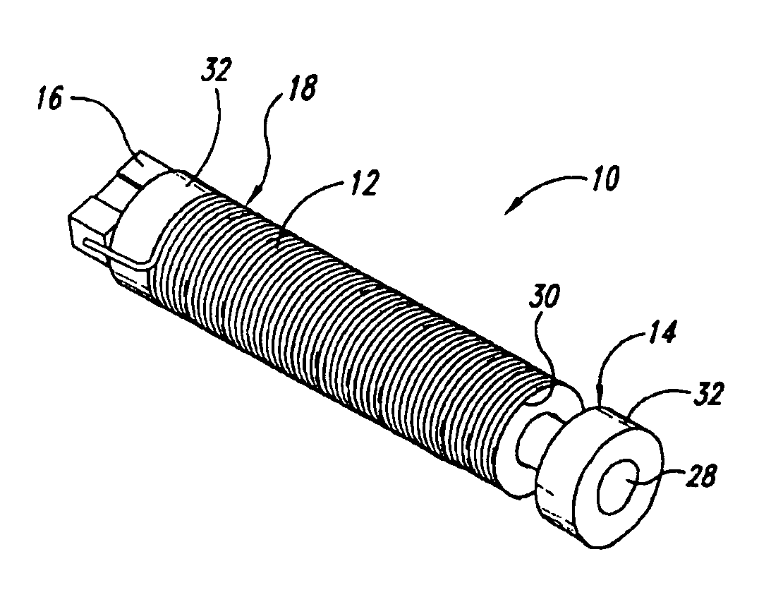
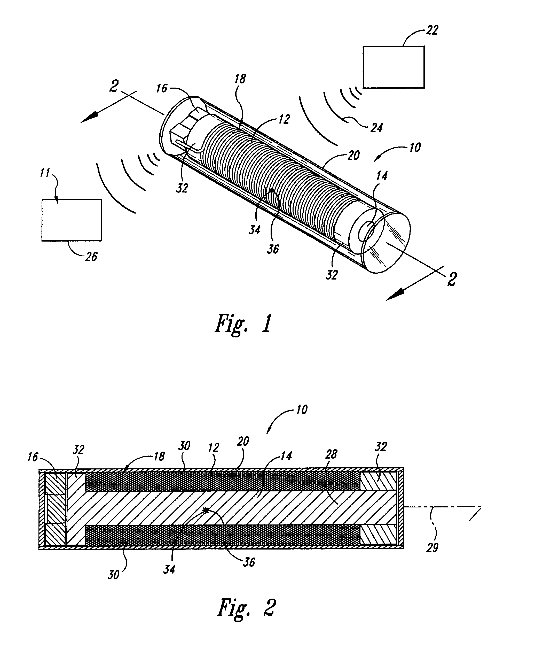
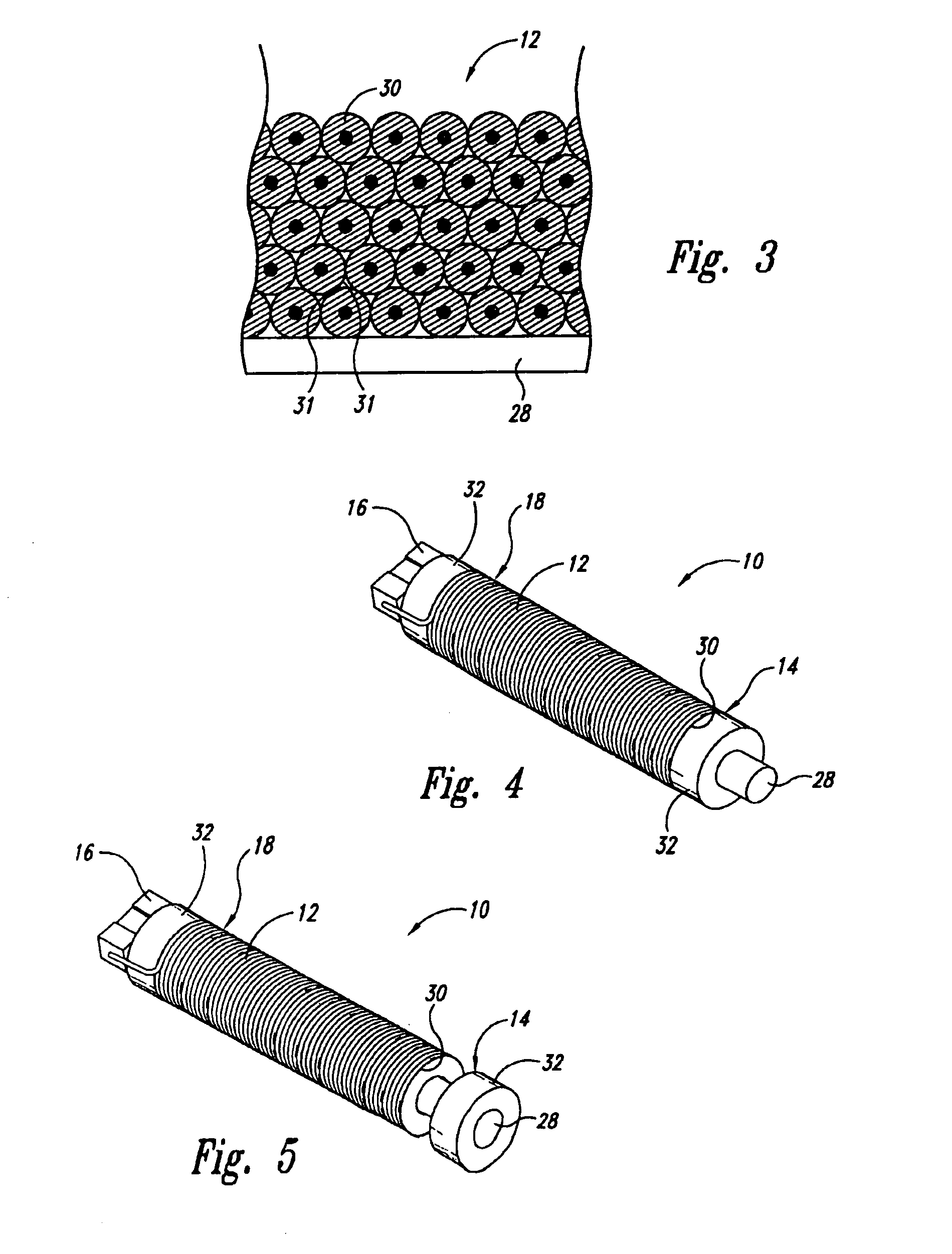
[0036]FIG. 1 is an isometric view of an implantable miniature resonating marker assembly 10 in accordance with one embodiment of the present invention. The marker assembly 10 is an inert, activatable assembly that can be excited to generate a signal at a resonant frequency detectable by a marker detection system external to the patient. An example of the marker detection system is described in detail in copending U.S. patent application Ser. No. 09 / 877,498, entitled Guided Radiation Therapy System, which...


PUM


Abstract

A miniature resonating marker assembly that includes, in one embodiment, a ferromagnetic core, a wire coil disposed around the core, and a capacitor connected to the wire coil adjacent to the magnetic core. The core, coil, and capacitor form a signal element that, when energized, generates a magnetic field at a selected resonant frequency. The magnetic field has a magnetic center point positioned along at least one axis of the signal element. An inert encapsulation member encapsulates the signal element therein and defines a geometric shape of the resonating marker assembly. The geometric shape has a geometric center point substantially coincident with the magnetic center point along at least a first axis of the signal element. The shape and configuration of the assembly also provides for a miniature signal element specifically tuned to resonate at a selected frequency with a high quality factor.

Description

TECHNICAL FIELD[0001]This invention relates to locating devices, and more particularly to miniature resonating marker assemblies and methods of tuning the same.BACKGROUND OF THE INVENTION[0002]Medical procedures often require locating and treating areas within a patient's body. Imaging systems, including x-ray, MRI, CT, and ultrasound have been used to help locate areas or particular targets within the body. While the imaging systems can be very useful in some situations, they can be limited to two dimensional information and may be unusable or difficult to use in certain procedures to provide real time three dimensional location information about a target.[0003]Many noninvasive medical procedures, such as radiation therapy and surgical procedures, require precise location information about the target to minimize the extent of collateral damage to healthy tissue around the target. Markers have been used to locate targets on and in a patient's body in preparation for a medical proced...

Claims


Application Information

Patent Timeline
IPC IPC(8): G08B13/14A61B5/055A61B5/06A61B19/00
CPCA61B5/6883A61B19/54A61B5/055A61B5/06A61B2019/5251A61B2019/5458A61B2034/2051A61B90/39A61B2090/3958A61B5/062H01Q1/2208H01Q7/08
Inventor GISSELBERG, MARGOHADFORD, ERICDIMMER, STEVEN C.GOLDBERG, JACKPELTON, JEFFZUBLIN, KURT
Owner VARIAN MEDICAL SYSTEMS
Why Eureka
Try Eureka