
Temperature recorder and temperature recording and controlling system for power supply equipment

a technology of temperature recording and control system, which is applied in the direction of instruments, heat measurement, air-break switches, etc., can solve the problems of unsatisfactory maintenance work, high work burden at the time of inspection, and dangerous inspection work, so as to reduce increase the operating ratio of monitoring devices.

Inactive Publication Date: 2006-11-14
SANYO ELECTRIC CO LTD
View PDF12 Cites 17 Cited by
  • Summary
  • Abstract
  • Description
  • Claims
  • Application Information

AI Technical Summary

Benefits of technology

[0005]It is a second object of the invention to provide a temperature recording and controlling system for power supply equipment, which can reduce the operating ratio of a monitoring device during power transmission in a normal temperature range and, upon the occurrence of an abnormal phenomenon such as abnormal heat generation in the power line, can promptly send information on this fact.
[0006]According to the invention, a temperature recorder provided with a memory for storing temperature records based on measurement with a temperature sensor is fixed to power supply equipment such as power lines. This temperature recorder wirelessly sends, at predetermined intervals, temperature records obtained by temperature measurement at predetermined measuring intervals to transmit the data to the monitoring device. By virtue of this construction, power supply equipment can be monitored without increasing the operating ratio of the monitoring device.

Problems solved by technology

In some installation environment or scale of the power supply equipment, however, satisfactory maintenance work cannot be carried out.
For example, in power supply equipment in a place between mountains, a high place, or a cold district of much snowfall, work burden at the time of inspection is large, and, in some weather or the like, inspection work is dangerous.
This leads to an increase in size and an increase in weight of the sensor and thus deteriorates the working efficiency of installation on the site.
Further, disadvantageously, the place where the sensor can be installed is restricted.
This poses a problem of increased operation cost.

Method used


Image

  • Temperature recorder and temperature recording and controlling system for power supply equipment
  • Temperature recorder and temperature recording and controlling system for power supply equipment
  • Temperature recorder and temperature recording and controlling system for power supply equipment

Examples


Embodiment Construction

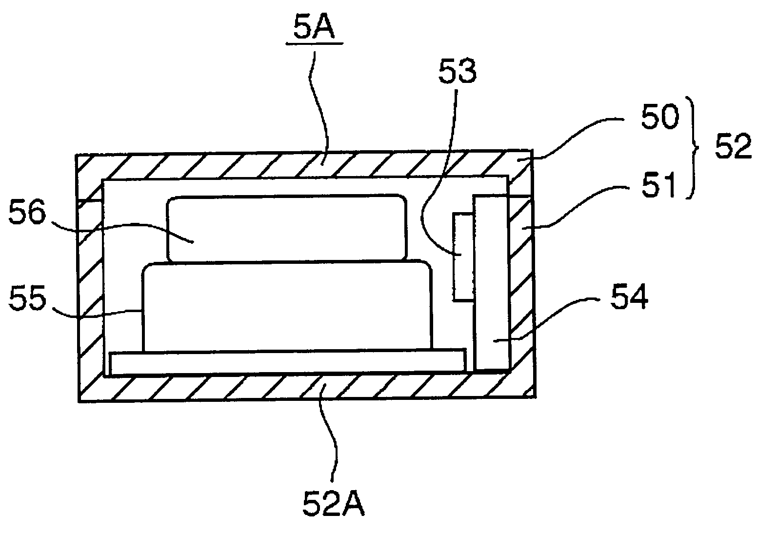
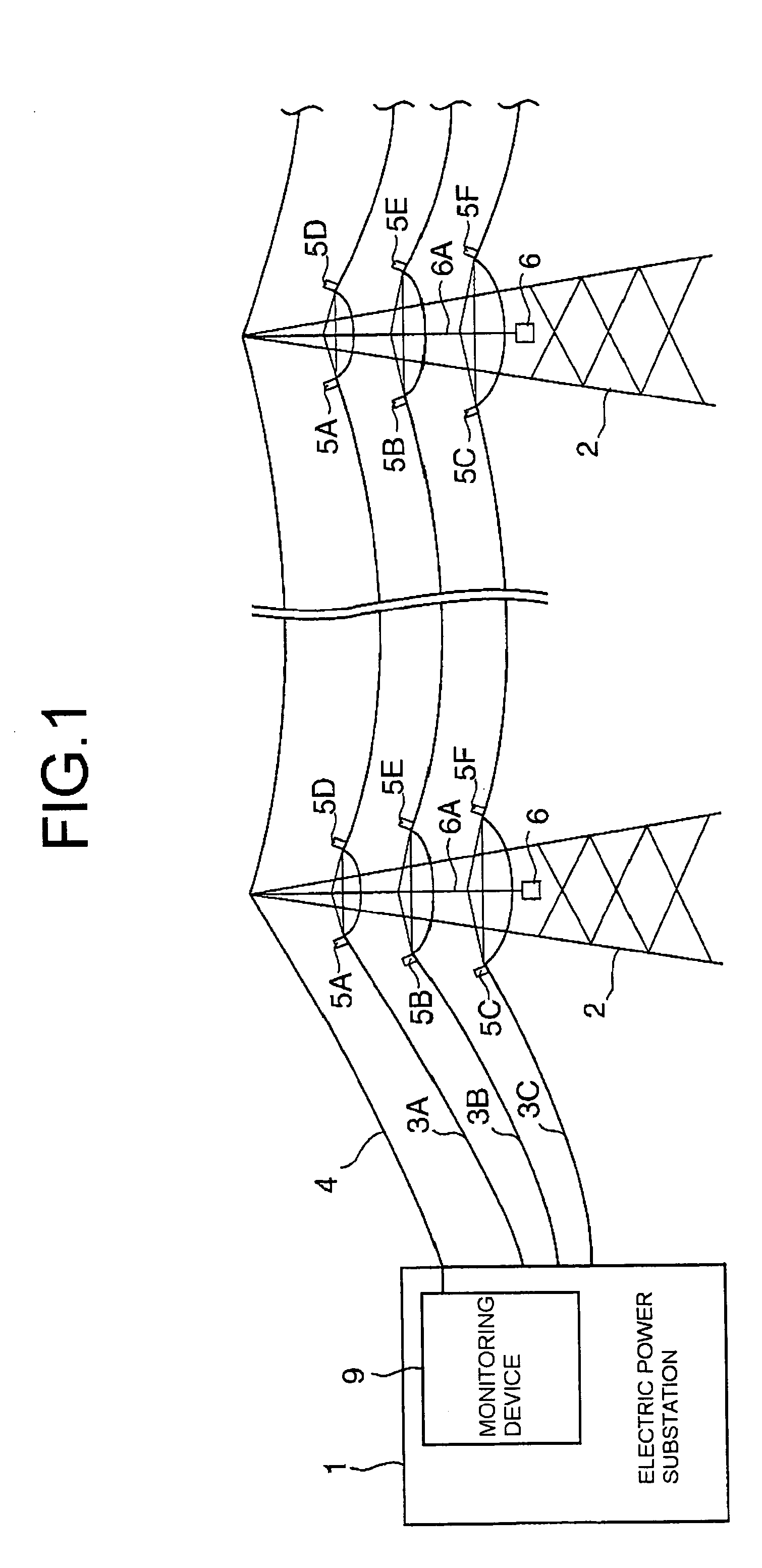
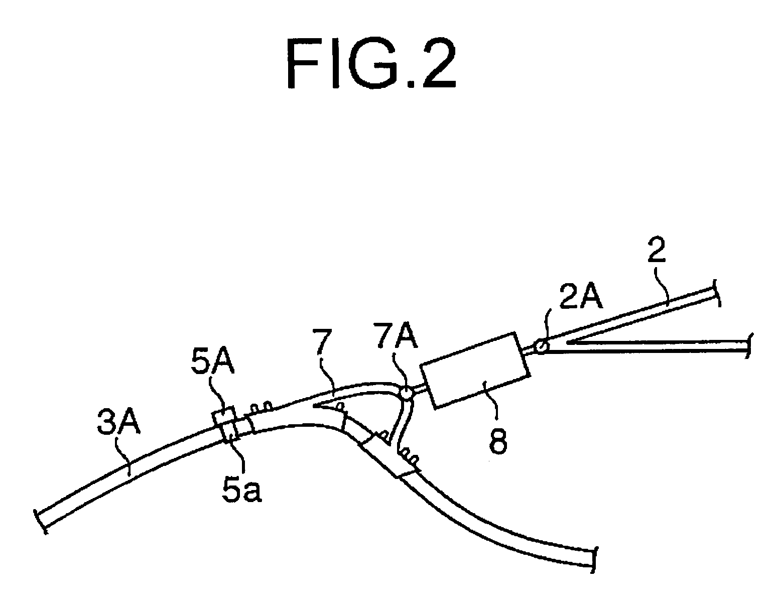
[0017]The temperature recorder and the temperature recording and controlling system for power supply equipment according to the invention will be explained in detail with reference to the accompanying drawings. FIG. 1 is a schematic diagram showing the construction of power supply equipment in an embodiment of the invention. The power supply equipment includes: an electric power substation 1 for transmitting electric power; power lines 3A, 3B, and 3C which have been extended from the electric power substation 1 through a power transmission tower 2; an optical fiber composite overhead earth-wire (OPGW) 4 provided on the top of the power transmission tower 2; temperature recorders 5A, 5B, 5C, 5D, 5E, and 5F which are installed respectively in the power lines 3A, 3B, and 3C in their tower supporting portions to detect the temperatures of the power lines 3A, 3B, and 3C, records the detected temperatures together with the measured time as temperature records in a temperature recording pa...


PUM

PropertyMeasurementUnit
length×35aaaaaaaaaa
temperatureaaaaaaaaaa
outer diameteraaaaaaaaaa

Abstract

A temperature recorder capable of storing, in time sequence, measured temperatures and measured times as temperature records in a memory incorporated therein, wherein, the temperature recorder is installed in a power line for temperature recording and, when the power line supplies a power in a normal temperature range, wirelessly transmits the temperature record to a monitor at a frequency of once every half day and, when an abnormal heating is detected from the power line, wirelessly transmits the temperature record as a temperature alarm record.

Description

TECHNICAL FIELD[0001]The invention relates to a temperature recorder, and a temperature recording and controlling system for power supply equipment, and more particularly to a temperature recorder, and a temperature recording and controlling system for power supply equipment, which monitor a change in temperature of power supply equipment such as power lines, insulators, and clamps.BACKGROUND ART[0002]In power supply equipment such as power lines and electric power substations, maintenance / inspection has hitherto been visually carried out mainly by a worker for inspection. In some installation environment or scale of the power supply equipment, however, satisfactory maintenance work cannot be carried out. For example, in power supply equipment in a place between mountains, a high place, or a cold district of much snowfall, work burden at the time of inspection is large, and, in some weather or the like, inspection work is dangerous. In order to solve the above problem, for example, ...

Claims


Application Information

Patent Timeline
Patent Type & Authority Patents(United States)
IPC IPC(8): G08C19/12G01K1/02
CPCG01K1/024G08C17/00
Inventor KAWAI, SIGEKAZUKURIBARA, HIROYUKIISHIKURA, TSUTOMU
Owner SANYO ELECTRIC CO LTD
Learn More