
Wind turbine generator

a wind turbine generator and generator technology, applied in the direction of electric generator control, machines/engines, mechanical equipment, etc., can solve the problems of inability to ensure the amount of electricity set in advance for wind conditions, the operation of the wind turbine generator must be halted, and the operating ratio decreases, so as to prevent snow accumulation and snow accumulation, improve the accuracy of detecting freezing, and increase the temperature

Inactive Publication Date: 2010-10-14
MITSUBISHI HEAVY IND LTD
View PDF6 Cites 4 Cited by
  • Summary
  • Abstract
  • Description
  • Claims
  • Application Information

AI Technical Summary

Benefits of technology

[0010]Against such a backdrop, it is required to reduce the operation halting time when the anemoscope / anemometer is frozen so as to minimize a decrease in operating ratio due to halting of the wind turbine generator.
[0011]The present invention is made in consideration of the above-described circumstances, and it is an object thereof to provide a wind turbine generator in which, even in a cold snowy environment in a cold region, the time required for recovering a frozen anemoscope / anemometer is reduced to minimize the decrease in operating ratio.
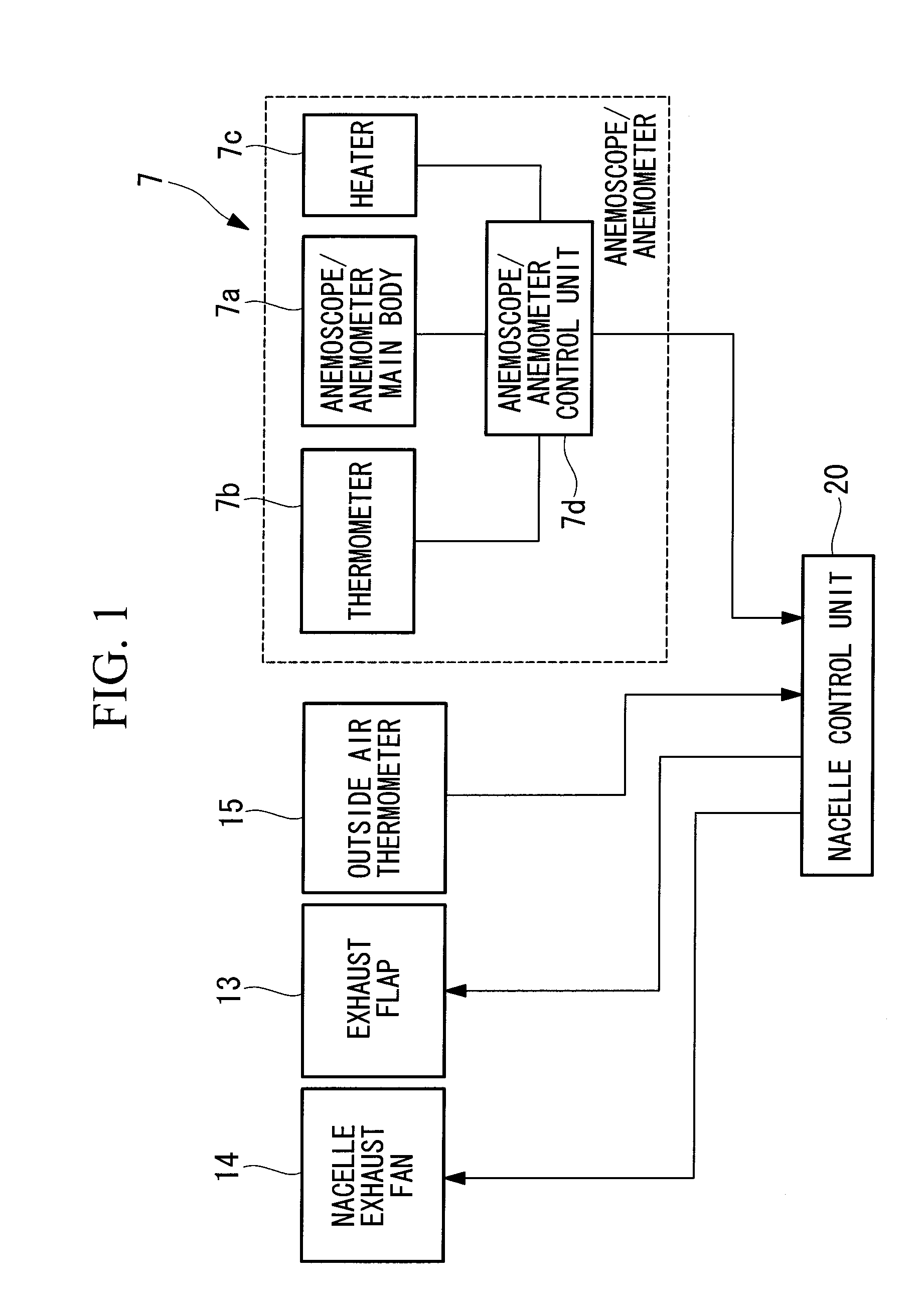
[0015]In the above wind turbine generator, it is preferable that a plurality of the anemoscope / anemometers be provided, and the ice and snow adhesion states of the anemoscope / anemometers be determined by comparing measured values. This can improve the accuracy of detecting the freezing or snowmelt adhesion states of the anemoscope / anemometers.
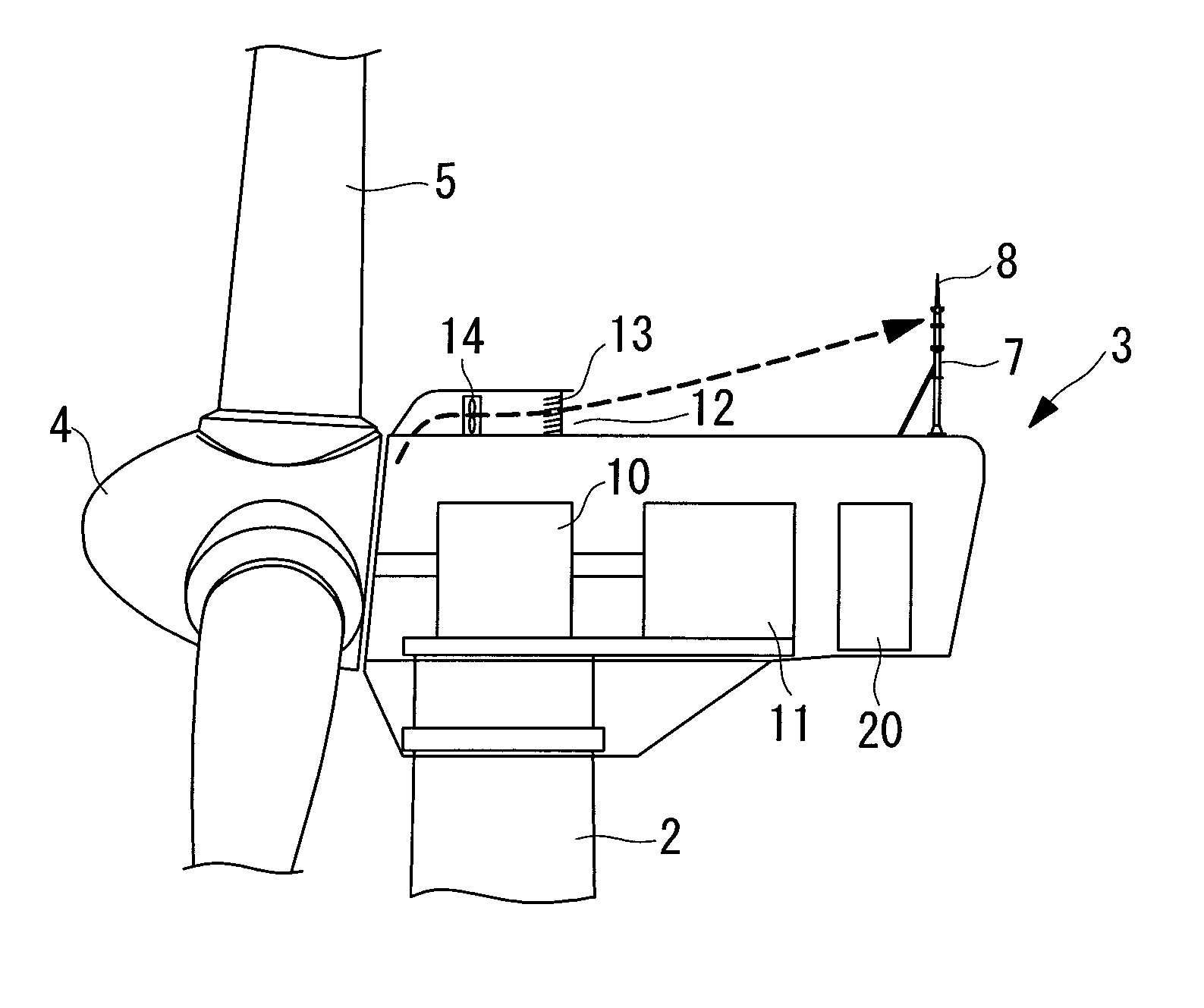
[0016]According to the present invention described above, when the anemoscope / anemometer is frozen, the in-nacelle cooling air outlet provided at the top of the nacelle so as to open in the direction of the anemoscope / anemometer can blow the in-nacelle cooling air toward the anemoscope / anemometer by directing the in-nacelle cooling-air blowing direction toward the anemoscope / anemometer by operating the cooling-air blowing-direction changing means. This allows the in-nacelle cooling air to be blown against the anemoscope / anemometer, which prevents snow buildup and snow accumulation by means of this flow or allows ice and snow adhering to the anemoscope / anemometer to be heated by means of the flow of the cooling air that has cooled the interior of the nacelle and increased in temperature.
[0017]Accordingly, the amount of snow buildup and the amount of snow accumulation can be reduced, and furthermore, melting of the ice and snow is accelerated by the heating by the in-nacelle cooling air in addition to the heating by the heater in the anemoscope / anemometer. As a result, ice and snow melting time is reduced, and thus the operation halting time of the wind turbine generator due to freezing of the anemoscope / anemometer is also reduced, and in particular, in the wind turbine generator installed in a cold snowy environment, a decrease in operating ratio due to the halted operation can be minimized.
[0018]Since a plurality of anemoscope / anemometers are provided at the top of the nacelle of the wind turbine generator, and ice and snow adhesion states of the anemoscope / anemometers are determined by comparing measured values; therefore, the accuracy of detecting the freezing or snowmelt adhesion states of the anemoscope / anemometers is improved, so that operating problems of the wind turbine generator due to the freezing or the like of the anemoscope / anemometers in a cold region can be reliably prevented.

Problems solved by technology

In such an installation environment, it sometimes takes much time to melt the snow or the like only with a heater mounted in the anemoscope / anemometer, during which the operation of the wind turbine generator must be halted because of adverse effects on the safety thereof.
As a result, if the freezing of the anemoscope / anemometer causes a state in which no measurement data can be obtained, the operating ratio decreases due to halting of the wind turbine generator, which causes a problem in that the amount of electricity that is set in advance for wind conditions cannot be ensured.

Method used


Image

  • Wind turbine generator
  • Wind turbine generator
  • Wind turbine generator

Examples


Embodiment Construction

[0039]An embodiment of a wind turbine generator according to the present invention will be described hereinbelow with reference to the drawings.

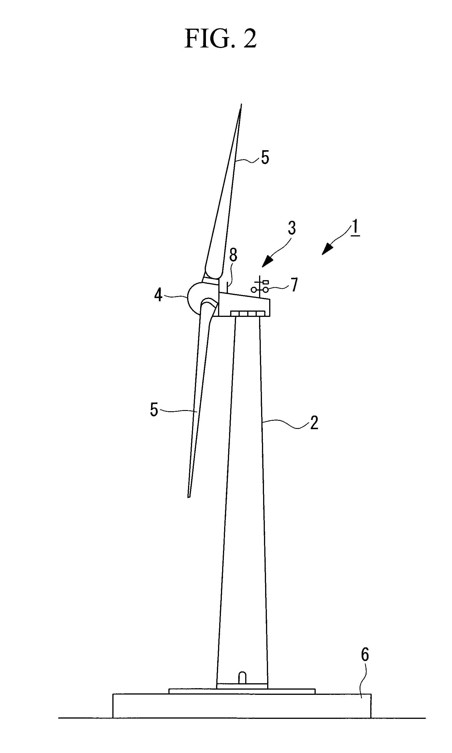
[0040]As shown in FIG. 2, a wind turbine generator 1 includes a tower 2 that is vertically erected on a foundation 6, a nacelle 3 mounted on the upper end of the tower 2, and a rotor head 4 mounted on the nacelle 3 so as to be rotatable about the substantially horizontal axis thereof.

[0041]The rotor head 4 has a plurality of wind turbine blades 5 mounted radially about its rotation axis. As a result, the power of wind blowing against the wind turbine blades 5 from the direction of the rotation axis of the rotor head 4 is converted to motive power that rotates the rotor head 4 about the rotation axis.

[0042]Anemoscope / anemometers 7 that measure the peripheral wind direction and wind velocity value and lightning rods 8 are provided at appropriate positions (for example, at the upper rear etc.) on the circumferential surface of the nacelle 3. In...


PUM


Abstract

A wind turbine generator is provided in which, even in a cold snowy environment in a cold region, the time required for recovering a frozen anemoscope / anemometer is reduced to minimize a decrease in operating ratio. A wind turbine generator is equipped with an anemoscope / anemometer (7) at the top of a nacelle that accommodates a driving and generating mechanism connected to a rotor head on which turbine blades are mounted, wherein an in-nacelle cooling air outlet that opens in the direction of the anemoscope / anemometer (7) is provided at the top of the nacelle, and the air outlet has exhaust flaps (13) serving as blowing-direction changing means for the cooling air.

Description

TECHNICAL FIELD[0001]The present invention relates to a wind turbine generator that generates electricity using a wind turbine that converts natural wind energy to rotational power.BACKGROUND ART[0002]A known wind turbine generator in the related art generates electricity using wind power, which is natural energy. This type of wind turbine generator is configured such that a nacelle mounted on a tower is provided with a rotor head fitted with wind turbine blades, a main shaft connected to the rotor head so as to rotate together therewith, a gearbox connected to the main shaft that rotates by receiving wind power with the wind turbine blades, and a generator driven by the shaft output power of the gearbox. In the thus-configured wind turbine generator, the rotor head having the wind turbine blades that convert wind power to rotational power and the main shaft rotate to generate shaft output power, and the shaft output power, which is increased in rotational speed through the gearbox ...

Claims


Application Information

Patent Timeline
Patent Type & Authority Applications(United States)
IPC IPC(8): F03D9/00F03D11/00
CPCF03D11/00F03D11/0025F05B2260/20Y02E10/726F05B2270/325Y02E10/721Y02E10/722F05B2260/64F03D80/40F03D80/60F03D80/30Y02E10/72F03D17/00F05B2270/32
Inventor MATSUSHITA, TAKATOSHI
Owner MITSUBISHI HEAVY IND LTD
Learn More