
Method for producing thin film

a technology of thin film and production method, which is applied in the direction of crystal growth process, polycrystalline material growth, chemically reactive gas growth, etc., can solve the problems of prolonging the entire processing time necessary for forming a film of a wafer as a product, lowering the operating ratio of the lp-cvd system, and raising the wafer production cost. , to achieve the effect of prolonging the entire processing time necessary for forming a film of a wafer as

Inactive Publication Date: 2002-12-12
RENESAS ELECTRONICS CORP
View PDF0 Cites 1 Cited by
  • Summary
  • Abstract
  • Description
  • Claims
  • Application Information

AI Technical Summary

Benefits of technology

[0017] However, since 25 dummy wafers need to be processed as the preparatory processing before processing the products, the entire processing time necessary for forming a film of a wafer as a product is prolonged. This leads to the lowered operating ratio of the LP-CVD system to raise the wafer production cost.
[0020] In accordance with the present invention, a thin film is formed on the wafer by chemical reaction under heat, following the start of the thin film forming process, through a pseudo process of suppressing variations in the film thickness caused by temperatures within the reaction temperature. This enables the processing of forming a thin film on a wafer which is to be a product to execute efficiently for reducing the process time and hence the operating ratio of the film forming device is enhanced.

Problems solved by technology

However, since 25 dummy wafers need to be processed as the preparatory processing before processing the products, the entire processing time necessary for forming a film of a wafer as a product is prolonged.
This leads to the lowered operating ratio of the LP-CVD system to raise the wafer production cost.

Method used


Image

  • Method for producing thin film
  • Method for producing thin film
  • Method for producing thin film

Examples


Embodiment Construction

[0030] Referring to the drawings, a preferred embodiment of the present invention will be explained in detail.

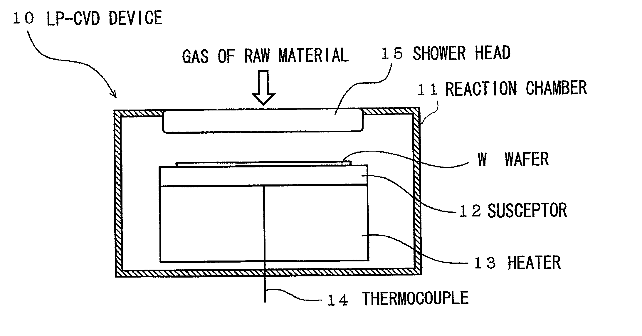
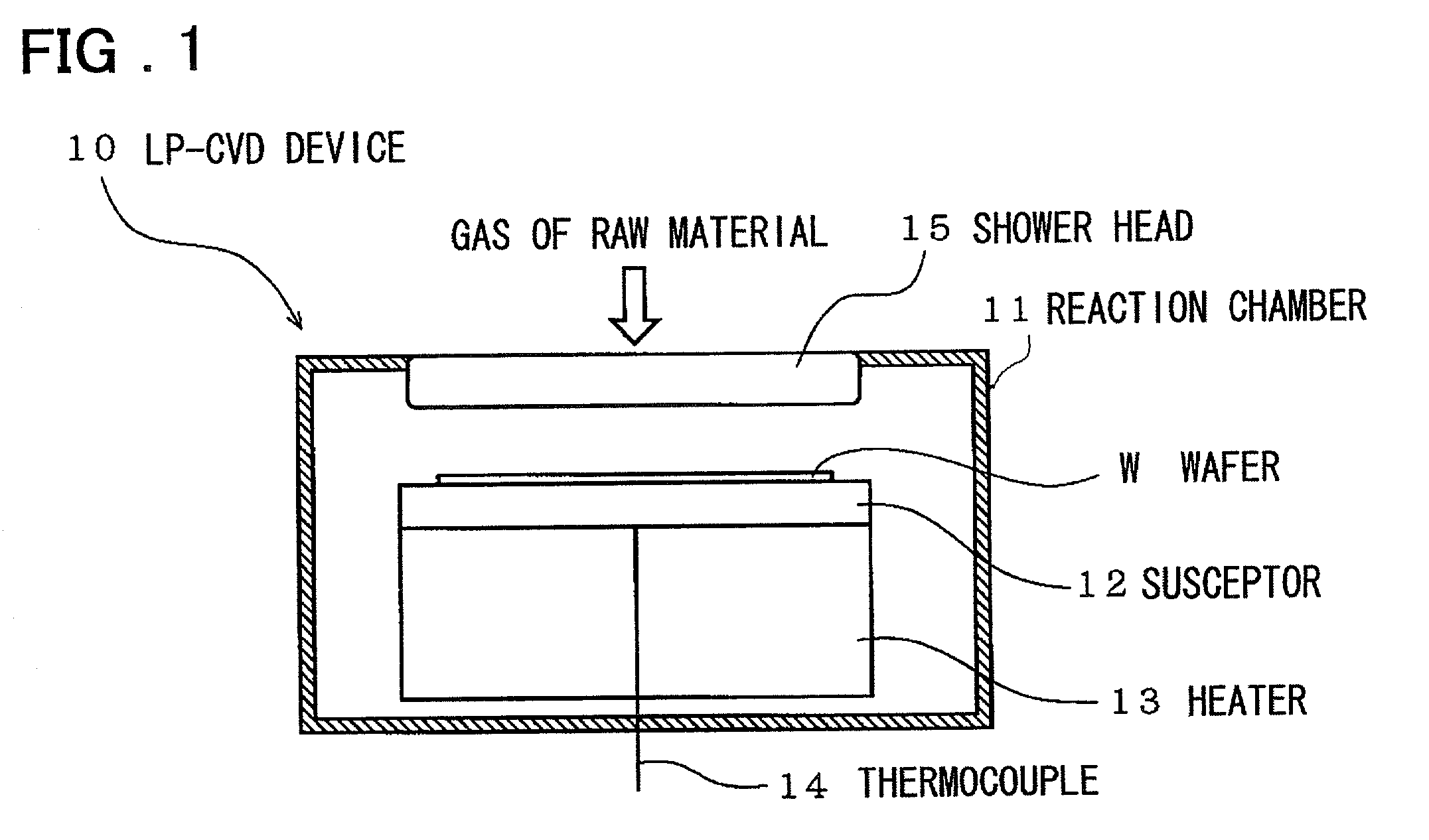
[0031] FIG. 1 shows a cross-sectional view showing a schematic structure of a manufacturing device used for practicing a method for manufacturing a thin film according to an embodiment of the present invention. As shown in FIG. 1, an LP-CVD device (thin film manufacturing device) 10 includes a susceptor 12 for holding a single type wafer W in a reaction chamber 11.

[0032] The susceptor 12 has, on its lower surface side, a heater 13 for heating the wafer W, held thereon, and a thermocouple (TC) 14 for temperature measurement, is arranged penetrating through the heater 13. Over the susceptor 12 there is provided a shower head 15 facing the wafer W as set on the susceptor 12. A raw material gas is supplied into the reaction chamber 11 through this shower head 15.

[0033] The process of forming a thin film on the single type wafer W by thermal reaction using this LP-CVD device 10, ...


PUM

PropertyMeasurementUnit
timeaaaaaaaaaa
timeaaaaaaaaaa
timeaaaaaaaaaa

Abstract

A thin film producing method in which the wafer film forming processing for a wafer to be a product may be carried out efficiently to shorten the processing time and to raise the operating ratio of the device. In a thin film deposition method using a single wafer processing for forming a thin film by chemical reaction under heat, a pseudo-process is provided which operates to suppress variations in the film thickness caused by the temperature in a reaction chamber 11. This pseudo process is the pre-heating processing of heating the reaction chamber 11 before actually charging the wafer W into the reaction chamber 11.

Description

[0001] This invention relates to a method for producing a thin film and, more particularly, to a method for forming a thin film on a wafer by chemical reaction under heat with a single wafer process.[0002] There has hitherto been known a method of producing a thin film on a wafer, by chemical reactions under heat, using a low-pressure chemical vapor deposition(termed as LP-CVD) system.[0003] In forming a thin film on a wafer, with a single wafer process by using a LP-CVD system, the following procedure is used. First, before proceeding to processing, the inside of a process chamber is evacuated to a low pressure and heated until the atmosphere in the chamber is stabilized at a preset temperature, in order to make preparations for film deposition.[0004] As the evacuated state is maintained, a single wafer is loaded into the chamber and held on a susceptor. Mixed gases are then introduced into the inside of the chamber. By introducing gases under a heated environment, a film depositio...

Claims


Application Information

Patent Timeline
Patent Type & Authority Applications(United States)
IPC IPC(8): C23C16/44C23C16/52H01L21/31H01L21/314H01L21/316H01L21/318
CPCC23C16/44H01L21/3185H01L21/31604C23C16/52H01L21/02263H01L21/0217
Inventor NAKAMURA, NAOKIFUKUMAKI, NAOMIABE, TAKAYUKI
Owner RENESAS ELECTRONICS CORP
Learn More