
Cooling System

a cooling system and cooling fluid technology, applied in the field of cooling systems, can solve the problems of large energy consumption compared with the conventional direct expansion type cooling system, and achieve the effect of running cost saving and reducing energy consumption

Inactive Publication Date: 2007-02-08
SANDEN CORP
View PDF3 Cites 8 Cited by
  • Summary
  • Abstract
  • Description
  • Claims
  • Application Information

AI Technical Summary

Benefits of technology

[0007] It is an object of the invention to provide a cooling system that can realize running cost saving by reducing energy consumption at the time of system operation.
[0009] In this cooling system, for example, in winter when the outdoor air temperature is low, heat exchange is performed between the brine and the outdoor air by the second heat exchanger to cool the brine. The cooling system can lower operating ratios of the compressor and the like by cooling the brine using the outdoor air. Since the operating ratios of the compressor and the like are lowered, the cooling system can reduce energy consumption at the time of system operation. Since the energy consumption at the time of system operation is reduced, the cooling system can realize running cost saving.

Problems solved by technology

However, since it is necessary to circulate the brine in the brine circuit, energy consumption is large compared with the conventional direct expansion type cooling system.

Method used


Image

  • Cooling System
  • Cooling System
  • Cooling System

Examples


Embodiment Construction

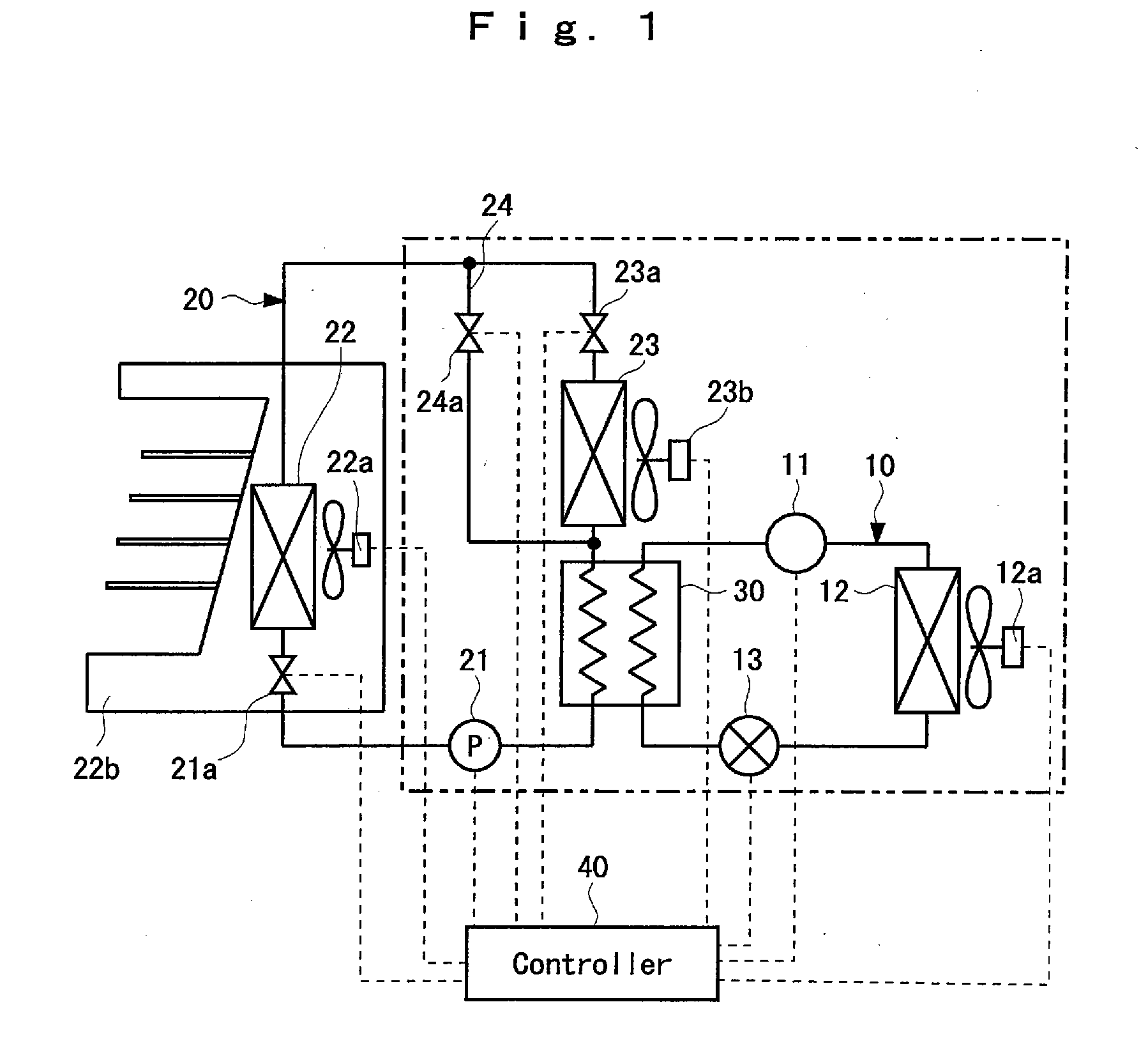
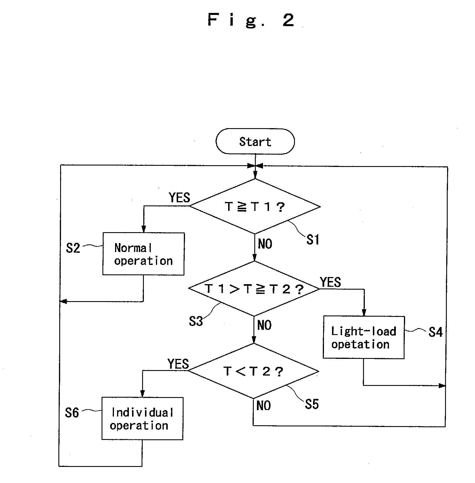
[0019]FIG. 1 to FIG. 5 shows a preferred embodiment of the invention.

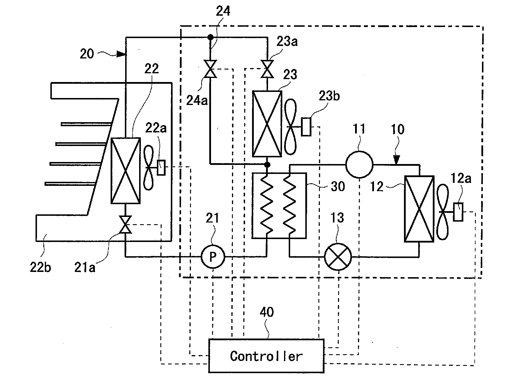
[0020] A structure of a cooling system using brine will be explained with reference to FIG. 1 and FIG. 2. The cooling system has a refrigerant circuit 10, a brine circuit 20, and a first heat exchanger 30.

[0021] The refrigerant circuit 10 has a compressor 11, a condenser 12, and an expansion valve 13. A refrigerant circulates to the compressor 11, the condenser 12, the expansion valve 13, the first heat exchanger 30, and the compressor 11 in this order. The condenser 12 has a first blower 12a. The first blower 12a forcibly brings the outdoor air into contact with the condenser 12. The refrigerant used in the refrigerant circuit 10 is Freon, non-Freon (e.g., ammonium), or the like.

[0022] The brine circuit 20 has a pump 21, a cooler 22, and a second heat exchanger 23 for performing heat exchange between the brine and the outdoor air. In the brine circuit 20, the brine circulates to the pump 21, the cooler 22, the ...


PUM


Abstract

A cooling system using brine includes: a refrigerant circuit that has a compressor, a condenser, and an expansion valve; a brine circuit that has a cooler and a pump for circulating the brine; a first heat exchanger that is shared by the refrigerant circuit and the brine circuit and performs heat exchange between a refrigerant flowing on a downstream side of the expansion valve of the refrigerant circuit and the brine flowing on a downstream side of the cooler of the brine circuit; and a second heat exchanger that is provided between the cooler and the first heat exchanger and performs heat exchange between the brine and the outdoor air.

Description

BACKGROUND OF THE INVENTION [0001] (i) Field of the Invention [0002] The present invention relates to a cooling system using brine. [0003] (ii) Description of the Related Art [0004] Conventionally, there is known a cooling system including a refrigerant circuit that has a compressor, a condenser, and an expansion valve, a brine circuit that has a pump and a cooler, and a first heat exchanger shared by the refrigerant circuit and the brine circuit. [0005] The cooling system performs, in the first heat exchanger, heat exchange between a refrigerant flowing on a downstream side of the expansion valve of the refrigerant circuit and brine flowing on a downstream side of the cooler of the brine circuit to cool the brine. The cooling system supplies the brine cooled to the cooler to cool articles stored in an apparatus, for example, a showcase, in which the cooler is set. [0006] The cooling system using brine is a cooling system proposed in response to the request for the post-Freon proces...

Claims


Application Information

Patent Timeline
IPC IPC(8): F25D17/02
CPCF25B2400/22F25B2600/11Y02B30/743F25B2700/2106F25D17/02F25B2600/111Y02B30/70
Inventor FUKUDA, TOSHIYUKIKOBAYASHI, MAKOTOTAKADA, KAZUMASA
Owner SANDEN CORP
Learn More