Method of and system for adaptive scatter correction in multi-energy computed tomography

a multi-energy computed tomography and scatter correction technology, applied in tomography, applications, instruments, etc., can solve the problems of plastic explosives presenting a particular challenge to baggage scanning systems, plastic explosives may be formed into geometric shapes that are difficult to detect, plastic explosive detection may be difficult, etc., to achieve the effect of improving the quality of z (effective atomic number) images

Inactive Publication Date: 2006-11-14
ANLOGIC CORP (US)
View PDF33 Cites 62 Cited by
  • Summary
  • Abstract
  • Description
  • Claims
  • Application Information

AI Technical Summary

Problems solved by technology

Plastic explosives, however, present a particular challenge to baggage scanning systems.
Due to their moldable nature, plastic explosives may be formed into geometric shapes that are difficult to detect.
The detection of plastic explosives may be difficult because it may be difficult to see the explosive material in the image, particularly when the material is disposed so that the thin sheet is parallel to the direction of the X-ray beam as the sheet passes through the system.
The requirement for such attentiveness can result in greater operator fatigue, and fatigue as well as any distractions can result in a suspected bag passing through the system undetected.
Accordingly, a great deal of effort has been made to design a better baggage scanner.
The images from the post-reconstruction analysis usually do not yield accurate estimates of the material's effective atomic number, and suffer low SNR (Signal to Noise Ratio) and many artifacts as well.
The iso-transmission line method requires a large amount of calibration data.
In such a situation, the linear equations are not valid and the method causes large approximation errors.
While most of the photons are attenuated within the scanned object, a small portion of photons are not absorbed, resulting in an increase in x-ray scatter received by the detectors.
Scatter causes artifacts in images reconstructed from the x-ray CT scanners.
It adversely affects image contrast and generates streaks from high-density objects.
Scatter also causes cupping and blurring similar to the beam hardening artifact in large bulk objects.
In dual energy CT scanners, the above mentioned artifacts caused by scatter are amplified by the dual energy decomposition procedure, resulting in degraded quality on the Z (effective atomic number) image.
An exact solution to the problems caused by scatter cannot be determined due to the randomness of the scattering process.
However, anti-scatter plates are extremely expensive and add structural complexity to the Even with anti-scatter plates, scatter still exists due to misalignment of the anti-scanners. scatter plates and finite height of the anti-scatter plates.
When the x-ray detector array has many rows of detectors, the scatter detectors can not be placed close enough to yield accurate measurement of the amount of scatter.
However scattering is a complicated, spatially-correlated process, and using a constant scatter value for all the detectors is not accurate enough for the generation of Z images in multi-energy CT scanners.

Method used


Image

  • Method of and system for adaptive scatter correction in multi-energy computed tomography
  • Method of and system for adaptive scatter correction in multi-energy computed tomography
  • Method of and system for adaptive scatter correction in multi-energy computed tomography

Examples


Embodiment Construction

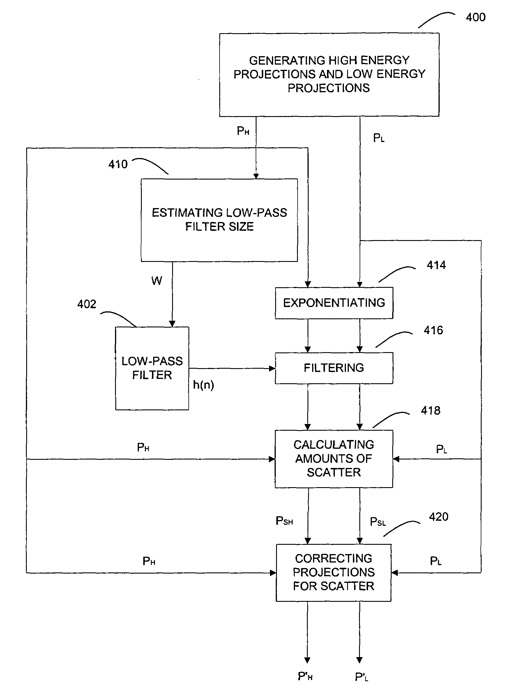
[0078]In accordance with the disclosure, an adaptive scatter correction algorithm for multi-energy projections is provided to better estimate amounts of scatter and correct for them, resulting in improved quality of Z (effective atomic number) images. The algorithm does not use scatter detectors to measure the amounts of scatter, but instead, estimates the amounts of scatter from the input projection data. The algorithm preferably takes the spatial correlation of the scattering process into account, and adaptively uses attenuations and shapes of scanned objects to estimate the amounts of scatter, thereafter correcting for them.

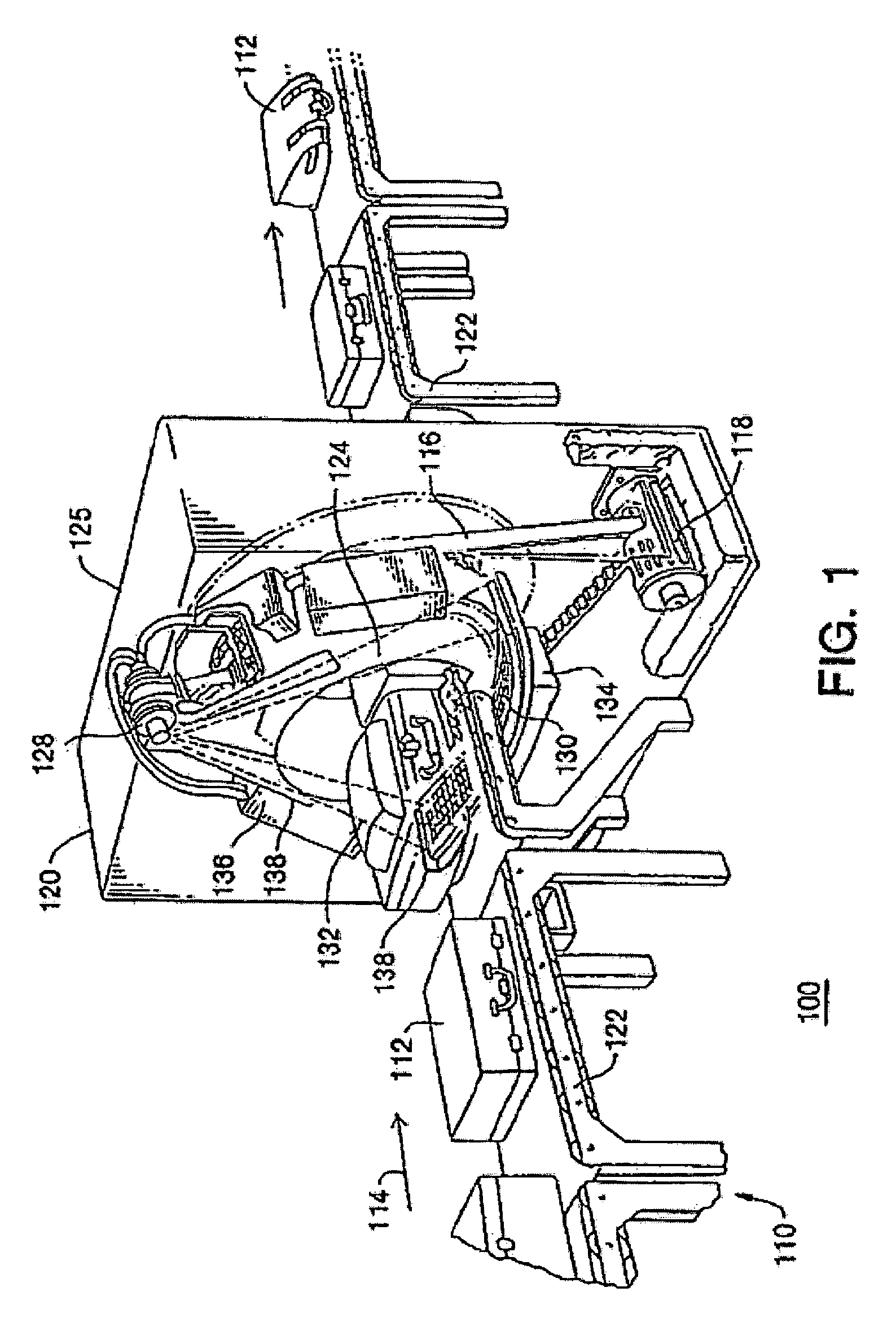
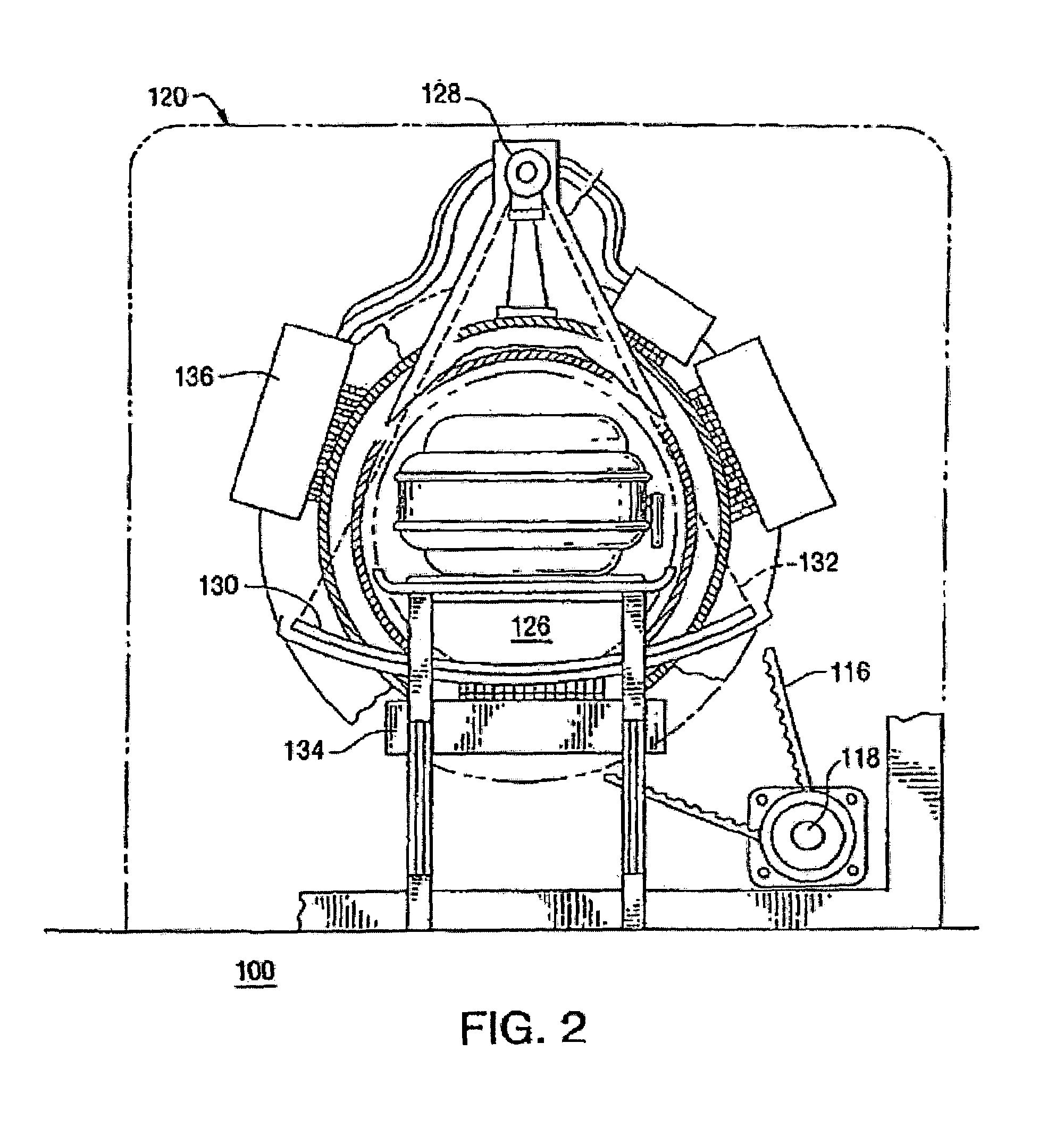
[0079]FIG. 6 illustrates the signal and data flow of the scanner system for explosive detection for the checked baggage for an airport of the present disclosure. Scanner 120 is typically similar to the one shown in FIG. 1 and has an X-ray source capable of producing a fan beam at two distinct energy levels (i.e., dual energy). DAS 134 gathers signals generated...


PUM

PropertyMeasurementUnit
atomic numberaaaaaaaaaa
energyaaaaaaaaaa

Abstract

Method of and system for adaptive scatter correction in the absence of scatter detectors in multi-energy computed tomography are provided, wherein input projection data acquired using at least two x-ray spectra for scanned objects may include a set of low energy projections and a set of high energy projections; wherein a low-pass filter of variable size is provided; the method comprises estimating the size of the low-pass filter; computing amounts of scatter; and correcting both sets of projections for scatter. The estimation of low-pass filter size comprises thresholding high energy projections into binary projections; filtering the binary projections; finding the maximum of the filtered binary projections; calculating the low-pass filter size from the found maximum. The computation of amounts of scatter comprises exponentiating input projections; low-pass filtering the exponentiated projections with the estimated filter size; computing the amounts of scatter from the filtered projections.

Description

RELATED APPLICATIONS[0001]This patent application and / or patents are related to the following co-pending U.S. applications and / or issued U.S. patents, of the same assignee as the present application, the contents of which are incorporated herein in their entirety by reference:[0002]“Nutating Slice CT Image Reconstruction Apparatus and Method,” invented by Gregory L. Larson, et al., U.S. application Ser. No. 08 / 831,558, filed on Apr. 9, 1997, now U.S. Pat. No. 5,802,134, issued on Sep. 1, 1998;[0003]“Computed Tomography Scanner Drive System and Bearing,” invented by Andrew P. Tybinkowski, et al., U.S. application Ser. No. 08 / 948,930, filed on Oct. 10, 1997, now U.S. Pat. No. 5,982,844, issued on Nov. 9, 1999;[0004]“Air Calibration Scan for Computed Tomography Scanner with Obstructing Objects,” invented by David A. Schafer, et al., U.S. application Ser. No. 08 / 948,937, filed on Oct. 10, 1997, now U.S. Pat. No. 5,949,842, issued on Sep. 7, 1999;[0005]“Computed Tomography Scanning Appar...

Claims


Application Information

Patent Timeline
Patent Type & Authority Patents(United States)
IPC IPC(8): A61B6/00A61B6/03G01N23/00G01N23/04G06T11/00
CPCA61B6/032A61B6/5282G01N23/046G06T11/005G06T2211/408G01N2223/419
Inventor YING, ZHENGRONGNAIDU, RAMSIMANOVSKY, SERGEYCRAWFORD, CARL R.
Owner ANLOGIC CORP (US)
Why Eureka
Try Eureka