Filter change indicator

a filter change indicator and indicator technology, applied in the field of fluid systems, can solve the problems of reducing engine efficiency and/or damage to the engine itself, clogging of fuel filters at various rates, and close tolerances that are easy to be damaged or disabled, and achieve the effect of efficient tuning

Inactive Publication Date: 2006-11-21
STANDYNE INC
View PDF8 Cites 11 Cited by
  • Summary
  • Abstract
  • Description
  • Claims
  • Application Information

AI Technical Summary

Benefits of technology

[0012]An object of the present invention is to provide a filter change indicator of a reliable construction, which undergoes a shape change in the presence of higher than normal pressure differentials across the filter.
[0013]Another object of the invention is to provide a filter change indicator that can be efficiently tuned to stamp out momentary pressure pulses.
[0014]A further object of the present invention is to provide a filter change indicator which changes shape in an incremental or otherwise step-like manner and in which may be incorporated physical features or markings such that the filter can be monitored as it becomes occluded.
[0015]A yet further object of the invention is to provide a new and improved filter change indicator which has an extended useful life and is highly reliable.

Problems solved by technology

These pumps have very close tolerances and may be easily damaged or disabled if particulate laden fuel is passed through them.
Interference with the passages, orifices or other structures of the injectors may result in a decrease in engine efficiency and / or damage to the engine itself.
Depending on such things as preventative maintenance scheduling, fuel quality, operating conditions, and the like, fuel filters become restricted or clogged at various rates.
Filter occlusion may adversely impact engine efficiency, and in some cases, may damage or destroy components of the engine.
In other cases, restriction of the filter can result in filter failure which may allow highly contaminated fluid to reach portions of the pump or injector system, resulting in extremely high repair costs for those devices.
As is well known in the relevant arts, the normal operation of equipment and associated fluid systems results in a buildup of material on equipment components that is often composed of oils and other fluids mixed with dust, dirt and particulates.
The inability to readily observe the indicator markings may lead to the filter check step of normal maintenance being eliminated, thus resulting in severe damage to the equipment during operation.
In addition, the principal composite materials of these conventional devices are limited to transparent plastic or glass material.
In particular, the plastic materials may be damaged by heat and / or abrasion to the point that visibility through the material is significantly degraded or no longer achievable.
In some instances, these electronic devices are not as dependable as mechanical indicators since a failure of the pressure transducer may occur without warning, thereby allowing an engine to be run with a heavily occluded filter, which can result in engine and / or injection system damage.
Another problem associated with detecting pressure differentials is the susceptibility to false indications caused by transient pressure pulses.

Method used


Image

  • Filter change indicator
  • Filter change indicator
  • Filter change indicator

Examples


Embodiment Construction

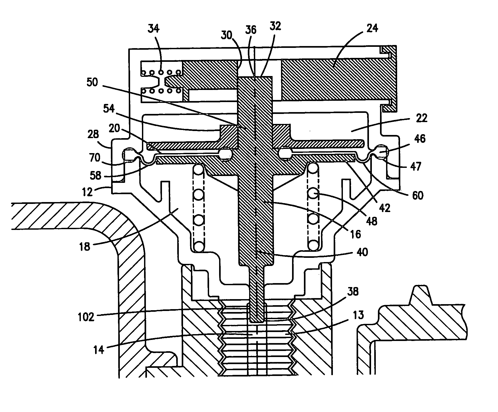
[0031]With reference to the drawings wherein like numerals represent like parts throughout the several figures, a filter change indicator in accordance with the present invention is generally designated by the numeral 10. The filter change indicator 10 is preferably incorporated into a filter system to provide a tactile indication of the filter condition to aid in the determination as to whether the filter requires replacement. The filter change indicator 10 has an efficient and low cost construction and is, for example, constructed from combinations of low cost materials such as plastic, metal, ceramic or other materials. For example, the principal material may be molded ABS plastic.

[0032]The filter change indicator 10 includes a graduated multi step housing 12, which partially forms a containment vessel or fluid portion 18. The exterior of the housing is preferably configured to be integrated into a fluid line, plenum or housing through such features as a threaded plug portion 13....


PUM

PropertyMeasurementUnit
timeaaaaaaaaaa
pressureaaaaaaaaaa
colorsaaaaaaaaaa

Abstract

A fluid system pressure indicator is adapted for use in fluid systems having a filter element. The fluid system force indicator includes a housing partitioned to be exposed to the fluid system to provide transmission of a mechanical force between these partitioned environments to indicate the fluid pressure. This exterior shape change is such that it can be identified through tactile means not requiring visual identification.

Description

FIELD OF THE INVENTION[0001]The present invention relates to fluid systems having a filtration device in which restriction of the filtration device can be determined by measurement of pressure. More specifically, the invention relates to devices for indicating whether a fluid filter is effective and / or requires replacement.BACKGROUND OF THE INVENTION[0002]Fluid systems requiring filtration apparatus are an integral part of the automotive and heavy equipment industries. Engine systems, hydraulic systems and various other collateral systems require fluids such as air, oil, fuel and coolants to be at least partially contained and directed to their functional end points.[0003]For instance, in engine systems utilizing diesel as fuel, extremely high pressure pumps are utilized. These pumps have very close tolerances and may be easily damaged or disabled if particulate laden fuel is passed through them. In addition, the fuel injectors of these engines are configured to deliver a spray of f...

Claims


Application Information

Patent Timeline
Patent Type & Authority Patents(United States)
IPC IPC(8): G01L7/16B01D35/00
CPCB01D35/143B01D65/10
Inventor JANIK, LEON P.VARDION, STEPHEN J.WILLIAMS, MICHAEL J.
Owner STANDYNE INC
Why Eureka
Try Eureka