Detection of faults in linear and rotary voltage transducers

a technology of rotary voltage transducer and fault detection, which is applied in the direction of transmission system, testing circuit, instruments, etc., can solve the problem that the shift in the sensed position value cannot be detected

Inactive Publication Date: 2006-11-21
GENERAL ELECTRIC CO
View PDF6 Cites 22 Cited by
  • Summary
  • Abstract
  • Description
  • Claims
  • Application Information

AI Technical Summary

Problems solved by technology

These wide range limits result, however, in detecting only extreme faults due to electrical open circuits or short circuits.
Failures which cause only minor shifts in the sensed position value may not necessarily be detected, even though such failures can impact control system operation.

Method used


Image

  • Detection of faults in linear and rotary voltage transducers
  • Detection of faults in linear and rotary voltage transducers
  • Detection of faults in linear and rotary voltage transducers

Examples


Embodiment Construction

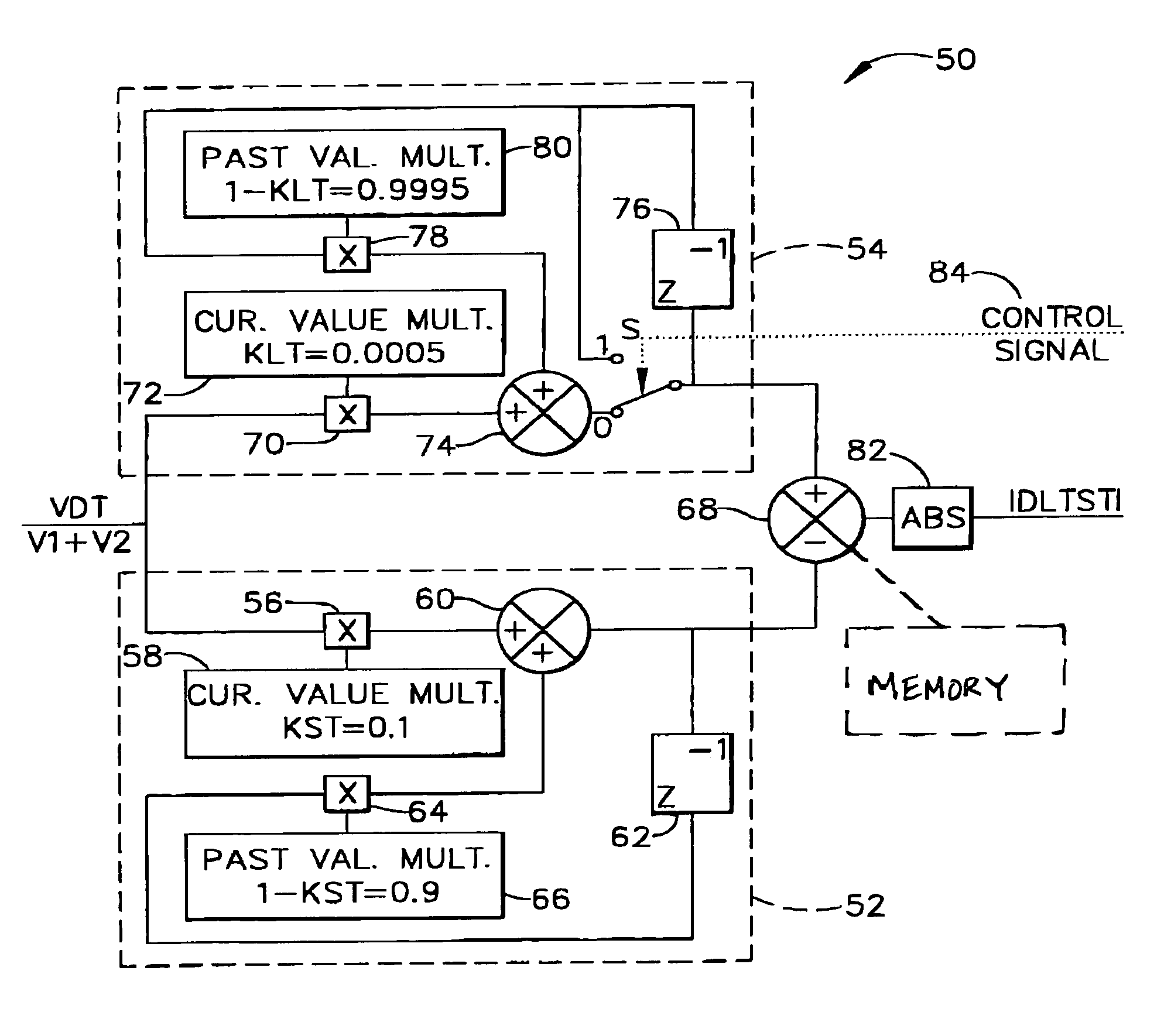
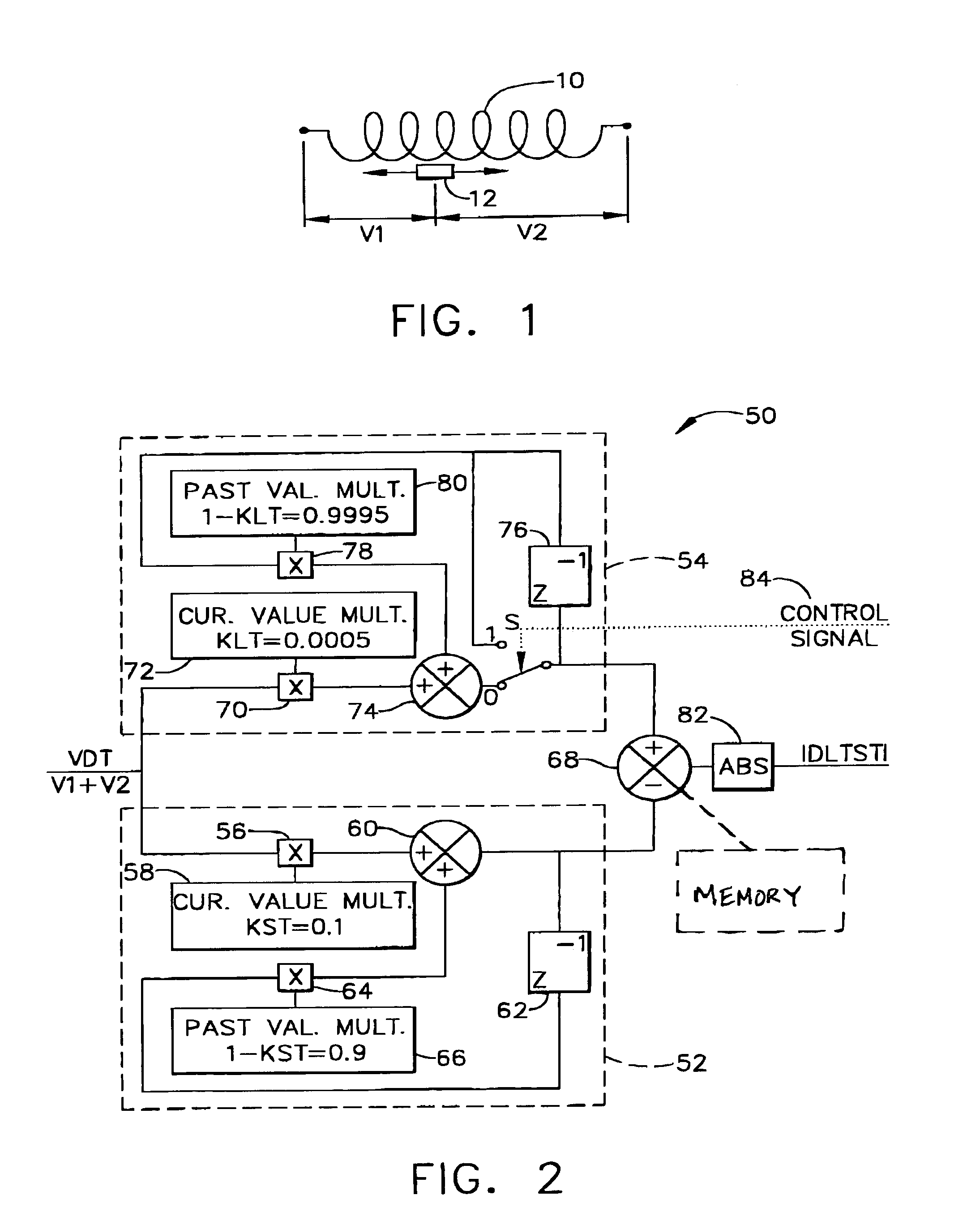
[0009]Generally, as shown in FIG. 1, an LVDT includes a secondary winding 10, and a movable core 12 within the LVDT that affects the output voltages V1 and V2. The sum of the voltages V1 and V2, however, remains constant provided there are no faults in windings 10. A secondary winding of an RVDT is configured identical to secondary winding 10 shown in FIG. 1.

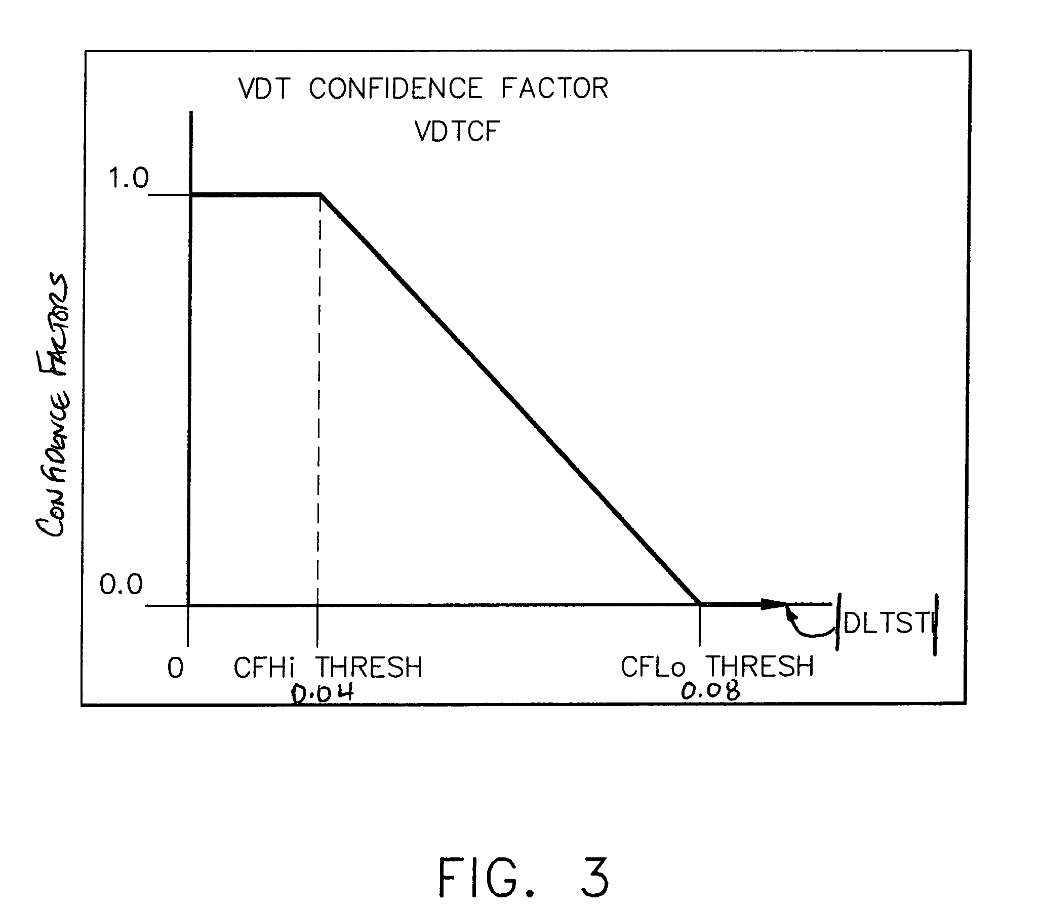
[0010]In accordance with one embodiment of the present invention, a sum of secondary voltages V1 and V2 is obtained by adding the secondary voltages together, i.e., V1+V2. Again, this sum of secondary voltages theoretically should be constant for all LVDT / RVDT positions, since the total length of the secondary transformer is constant. An electrical fault in the primary or secondary windings will generate a corresponding change in the sum of secondary voltages. By comparing this shifted value to a reference value which is representative of a no-fault condition, an error value is created which indicates the magnitude of the shift ...


PUM


Abstract

Systems and methods for detecting faults in RVDTs and LVDTs are described. In an exemplary embodiment, a sum of secondary voltages V1 and V2 from a transducer is obtained by adding the secondary voltages together, i.e.; V1+V2. This sum of secondary voltages theoretically should be constant for all LVDT/RVDT positions, since the total length of the secondary transformer is constant. An electrical fault in the primary or secondary windings generates a corresponding change in the sum of secondary voltages. By comparing this shifted value to a reference value which is representative of a no-fault condition, an error value is created which indicates the magnitude of the shift in the sum of the secondary values. Depending upon the magnitude of the error value, certain actions are taken.

Description

BACKGROUND OF THE INVENTION[0001]The present invention relates generally to control systems for position sensing, and more specifically, to detecting faults in linear variable differential transformers and rotary variable differential transformers.[0002]Position sensors are utilized in many different applications, including in gas turbine engines for aeronautical, marine, and industrial applications. Such engines often include, for example, rotary voltage differential transducers (RVDTs) and linear voltage differential transducers (LVDTs). The transducers are coupled to actuators, and provide a voltage signal proportional to a stroke position of the actuator.[0003]To detect faults in RVDTs and LVDTs, a range test can be performed on the sum of secondary voltages from the transducers. A range test also can be performed on a sensed position to verify signal integrity. The range limits, however, must be set wide enough to account for all worse-case system variations. Otherwise, a prope...

Claims


Application Information

Patent Timeline
Patent Type & Authority Patents(United States)
IPC IPC(8): H02H3/26G01B7/00G01R33/00G01B7/30G01D1/18G01D3/08G01D5/20G01D5/22G08C25/00
CPCG01D1/18G01D3/08G01D5/2208
Inventor COOK, KENNETH F.WITTENBACH, ROBERT D.
Owner GENERAL ELECTRIC CO
Why Eureka
Try Eureka