
Method and apparatus for modifying wake

Active Publication Date: 2006-11-28
MALIBU BOATS
View PDF12 Cites 78 Cited by
  • Summary
  • Abstract
  • Description
  • Claims
  • Application Information

AI Technical Summary

Benefits of technology

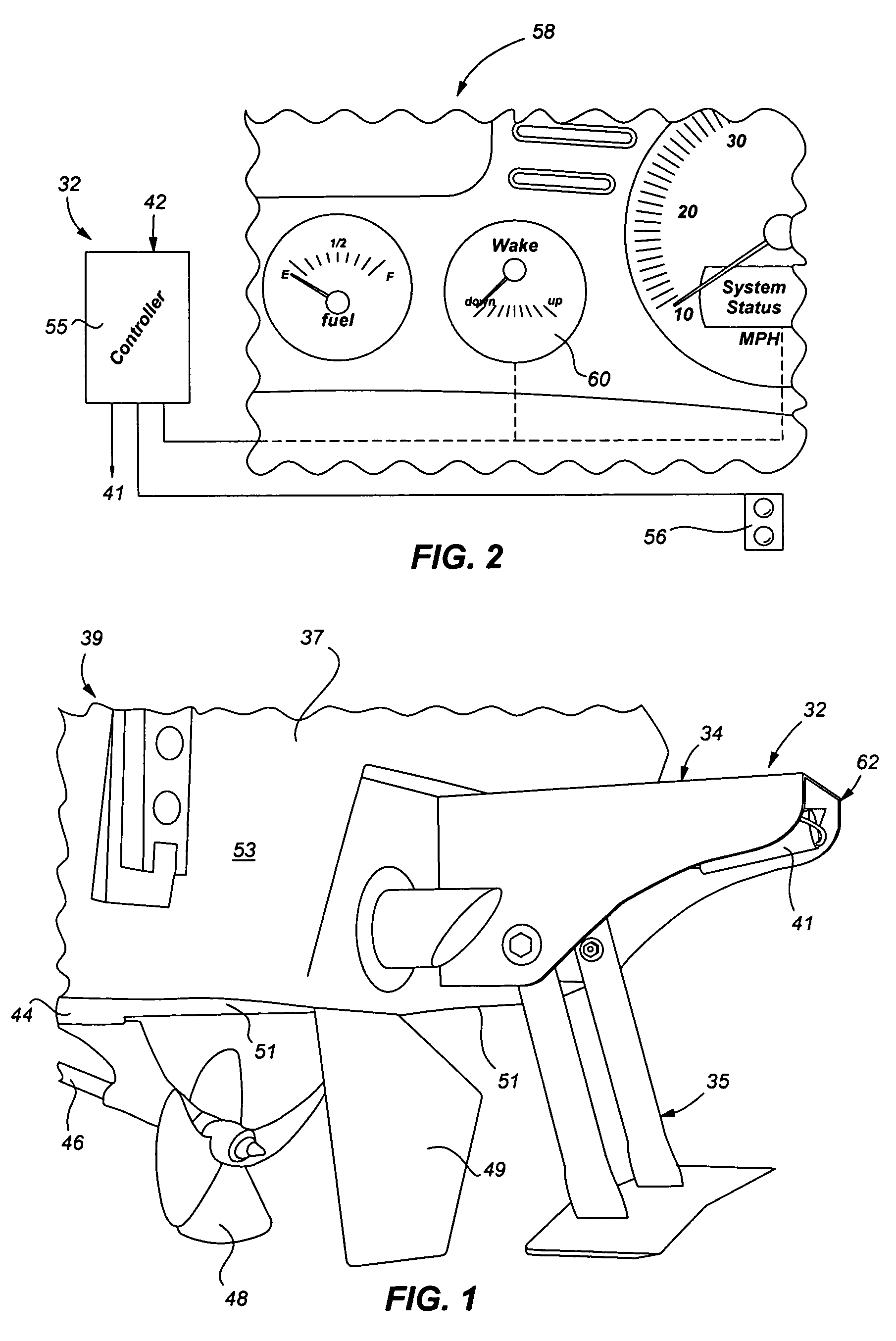
[0018]The controller may be configured to control the actuator in response to one or more operational parameters of the watercraft. The controller may be configured to prohibit the actuator from moving the linkage and foil between the stored position and active area unless speed of the watercraft may be less than a predetermined threshold speed. The predetermined threshold speed may be approximately 10 miles per hour. The controller may be configured to allow the actuator to move the linkage and foil between a plurality of active positions within the active area when the speed of the watercraft may be above the predetermined threshold speed but below a predetermined maximum speed. The predetermined maximum speed may be approximately 25 miles per hour. The controller may be configured to prevent the actuator to move the linkage and foil between a plurality of active positions within the active area when the speed of the watercraft may be greater than approximately 10 miles per hour. The controller prohibits the actuator from moving the linkage and the foil when the speed of the watercraft may be approximately zero.
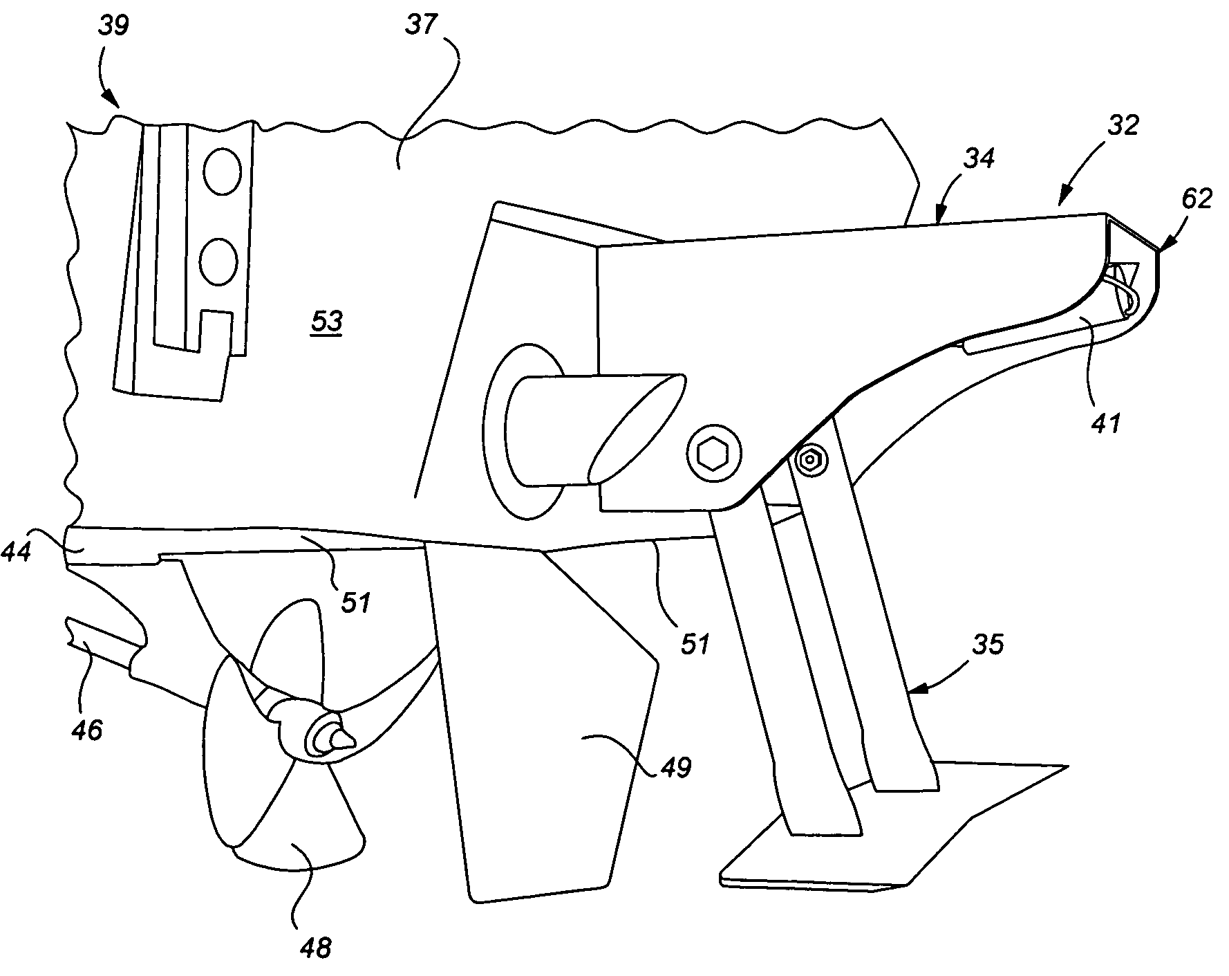
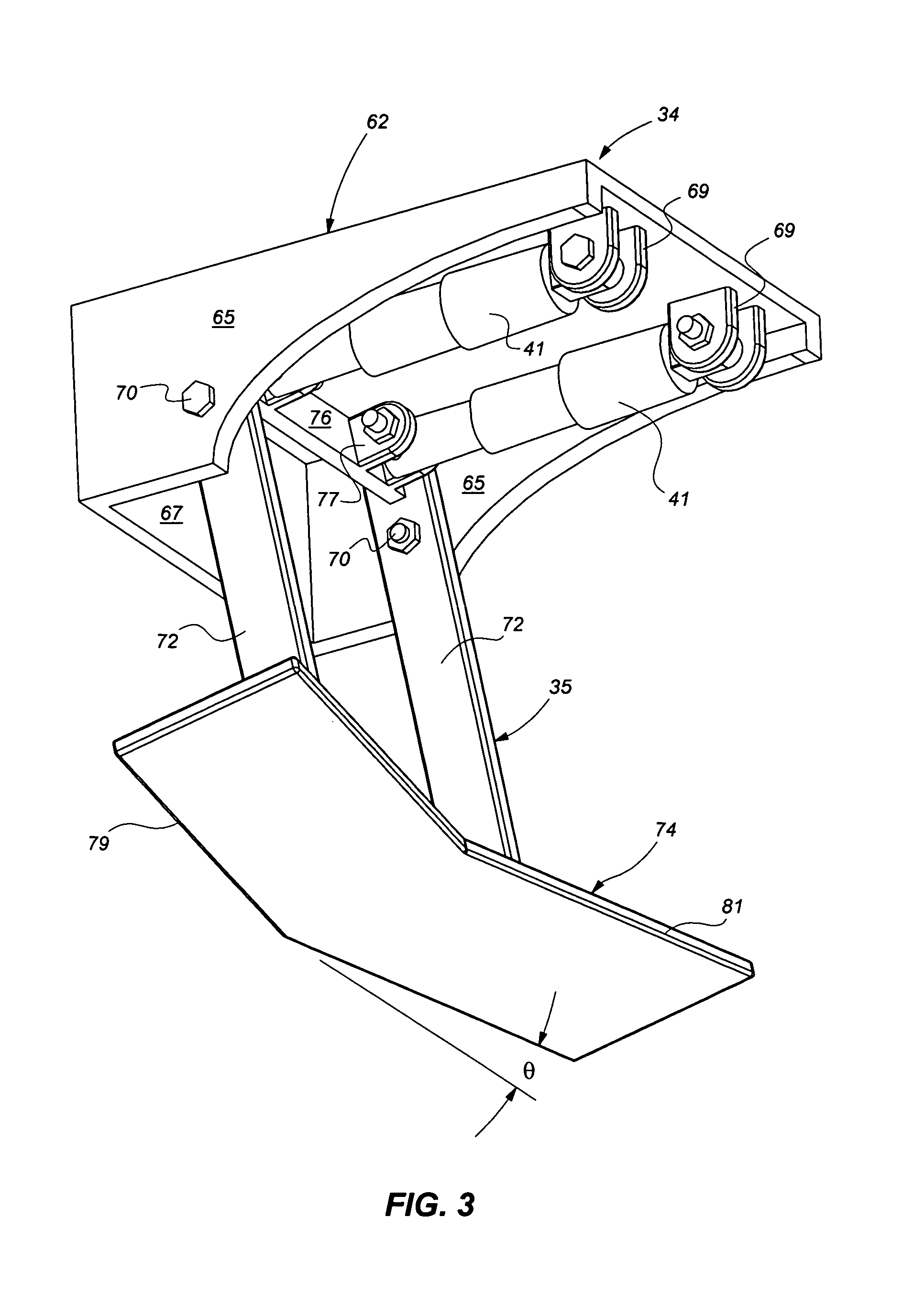
[0019]Another aspect of the present invention is directed to a wake modifying system for modifying a wake produced by a watercraft moving through water. The system includes a mounting body, the mounting body being configured to be secured to the watercraft, a linkage including an arm being pivotably attached at an upper end thereof to the mounting body, a water foil attached to a lower end of the arm, the water foil being dimensioned and configured for movement between a stowed position adjacent the mounting body and an active area below the mounting member, the water foil being configured for enhancing the wake produced by the moving watercraft, and an actuator pivotably attached at one end to the mounting body and pivotably attached at another end to the arm adjacent the upper end. The actuator may be configured for positioning the arm and the water foil in response to a control signal.
[0020]The mounting body may be secured to a transom of the watercraft. The linkage may include a pair of arms, each arm being pivotably attached at an upper end thereof to the mounting body and attached at a lower end thereof to the water foil, wherein the actuator may be configured to stow between the pair of arms when the foil may be in the stowed position. In the stowed position, the actuator may be positioned substantially within a cavity formed by the mounting body and the pair of arms, and the foil may be positioned aft of the mounting body. The mounting body may include a forward mounting plate, opposing sidewalls extending from side edges of the mounting plate, each sidewall having a pivot point for pivotal at

Problems solved by technology

As the sport has matured, wakeboard enthusiasts have developed increasingly complex tricks like spins, grabs, and flips.
The additional weight lowers the stern of the boat during towing and increases the size of the wake, however, there are several disadvantages to this method.
This is disadvantageous when the boat is used for cruising rather than skier towing.
It can also be disadvantageous when one desires to use the same boat for pulling wakeboarders at slower speeds with a larger wake and skiers at high speeds with a small wake.
One cannot increase or decrease the wake size and maintain a top cruising speed without stopping ashore to load or unload the weights.
Furthermore, the additional weight poses a safety risk.
Every boat has a maximum load capacity, and the additional weight lowers the margin of safety.
Because these boats do not employ a deep V-shaped hull, they have lower top speeds typically under 50 mph.
These boats are said to run “wet,” meaning that they have high drag from the added area contacting the water surface.
Generally, these devices and designs minimize the wake size, which is not desirable for wakeboarding and trick skiing.
However, all the hull designs require a tradeoffs between speed and wake size.
These hydrofoil devices increase downforce on the boat hull and in turn increase the wake size.
Fixed hydrofoil devices are limited in that they do not allow for adjustment of the wake size; the single position of the hydrofoil allows for only a single wake size at a particular speed.
In particular, known hydrofoil devices either require manual removal of the hydrofoil at cruising speed or they cannot be removed at all.
Thus, known hydrofoil devices are fixed or cannot be easily adjusted between cruising and towing conditions.
This device has the limitation of requiring users to wait for the bladder to be filled and emptied and also has limited adjustability.
Moreover, the increased weight of the bladder also lowers the loading margin of safety as discussed.

Method used


Image

  • Method and apparatus for modifying wake
  • Method and apparatus for modifying wake
  • Method and apparatus for modifying wake

Examples


Embodiment Construction

[0032]Reference will now be made in detail to the preferred embodiments of the invention, examples of which are illustrated in the accompanying drawings. While the invention will be described in conjunction with the preferred embodiments, it will be understood that they are not intended to limit the invention to those embodiments. On the contrary, the invention is intended to cover alternatives, modifications and equivalents, which may be included within the spirit and scope of the invention as defined by the appended claims.

[0033]For convenience in explanation and accurate definition in the appended claims and detailed description, the terms “up” or “upper”, “down” or “lower”, “inside” and “outside”, “fore” or “forward” and “aft” are used to describe features of the present invention with reference to the positions of such features as displayed in the figures.

[0034]While reference will be made to towing a wakeboarder, it will be understood that the present invention can be applied ...


PUM


Abstract

An adjustable wake setting device for modifying a wake produced by a watercraft traveling through water. The system has a mounting member dimensioned and configured for attachment to the watercraft, a foil dimensioned and configured for movement between a stowed position adjacent the mounting member, out of the water, and an active area below the mounting member, in the water, such that the foil adjusts a relative position of the watercraft in the water thereby modifying the wake produced by the water craft traveling through the water, a linkage movably securing the foil to the mount, the linkage being dimensioned and configured for adjustably positioning the foil in the stowed position and the active area, an actuator mounted on the mounting member and connected to the linkage for moving the linkage such that the foil moves between the stowed position and the active area, and a controller for selectively actuating the actuator thereby selectively moving the foil between the stowed position and the active area. A method of using the adjustable wake setting device is also disclosed.

Description

TECHNICAL FIELD[0001]This invention relates, in general, to methods and apparatus for modifying wakes, and more particularly to remotely adjusting the wake behind powerboats towing wake boarders and water-skiers.BACKGROUND OF THE INVENTION[0002]In water sports, a typical tow boat is operated at speeds in excess of 15 mph. At these speeds, the boat hull creates a trailing wake with a low, turbulent middle developing near the stern of the boat. The outer edge of the wake forms a V-shaped lip with water outside the middle of the wake.[0003]As a boat travels through the water, the stern of the boat hull lowers in the water and the bow rises at an angle of attack to oncoming water. The stern of the boat hull displaces water, which effectively creates the wake behind the boat. A heavier boat lying lower in the water will create a larger wake due to the greater water displacement. The shape of the hull also affects the wake shape and size.[0004]While often referred to generically as “water...

Claims


Application Information

Patent Timeline
IPC IPC(8): B63B1/30B63B1/22B63B34/56
CPCB63B1/18B63H25/44B63B34/75B63B39/061
Inventor GASPER, DANIEL L.
Owner MALIBU BOATS
Learn More