Wake control mechanism

a control mechanism and wake technology, applied in the direction of special-purpose vessels, vessel construction, vessel movement reduction by foils, etc., can solve the problem of increasing the wake size by adding weight, and achieve the effect of lowering the boat rear, little weight, and rapid adjustmen

Inactive Publication Date: 2005-07-21
MOORE STEVEN CLAY
View PDF21 Cites 68 Cited by
  • Summary
  • Abstract
  • Description
  • Claims
  • Application Information

AI Technical Summary

Benefits of technology

[0004] The present invention achieves the same lowering of the boat rear that is achieved by a bladder, but without the added weight. The invention accomplishes this with one or more wake control plates, hereafter called plates, which look similar to normal trim tabs, but they have the opposite effect of trim tabs used so far, because: 1) the plates which are the subject of this patent are mounted so their front edge can be below the top surface of the flow of water beneath the hull of the boat versus normal trim tabs which are flush with the bottom of the hull, and 2) the plates are tilted up (back end higher than front edge) instead of down (back lower than front edge) so that the water can be scooped up instead of pushed down. This has the effect of forcing the back of the boat deeper into the water, just as added weight does, instead of lifting the stem as a normal trim tab does. The main advantages are: relatively little weight is added to the boat; more rapid adjustability; greater control of wake size; the plates can be adjusted to create different wake shapes compared to bladders which merely increase wake size; and the plates have dual use because they can be positioned so as to act like traditional trim tabs thus eliminating the need for normal trim tabs. No other inventions or designs found in patent searches describe plates or anything else designed to have negative lift by a water-scooping action.
[0005] The plates may be any size and may be connected to the stern and adjusted to various positions in a variety of ways, so that the front edge of the wake control plate(s) can be submersed in the water flowing past the boat, under the hull, behind the stern and / or to the sides of the stem, at an angle which provides a scooping action . . . the opposite of the lifting action of normal trim tabs. Additionally the plates may have walls allowing the water scooped up by the plates to accumulate above water level, thus increasing wake size by adding weight. It is the water scooping effect which is the object of this invention, regardless of what portion of the plates are in front, beside or behind the stern.

Problems solved by technology

Additionally the plates may have walls allowing the water scooped up by the plates to accumulate above water level, thus increasing wake size by adding weight.

Method used


Image

  • Wake control mechanism
  • Wake control mechanism
  • Wake control mechanism

Examples


Embodiment Construction

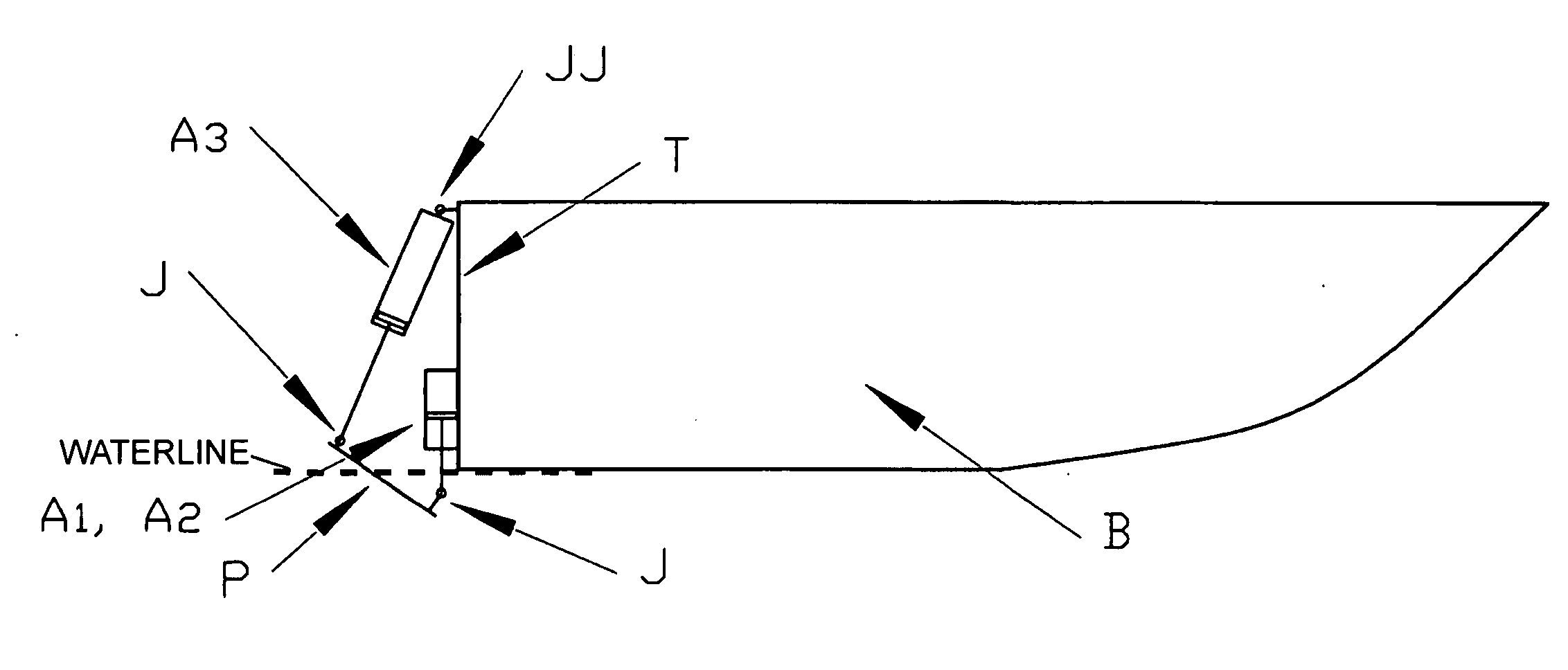
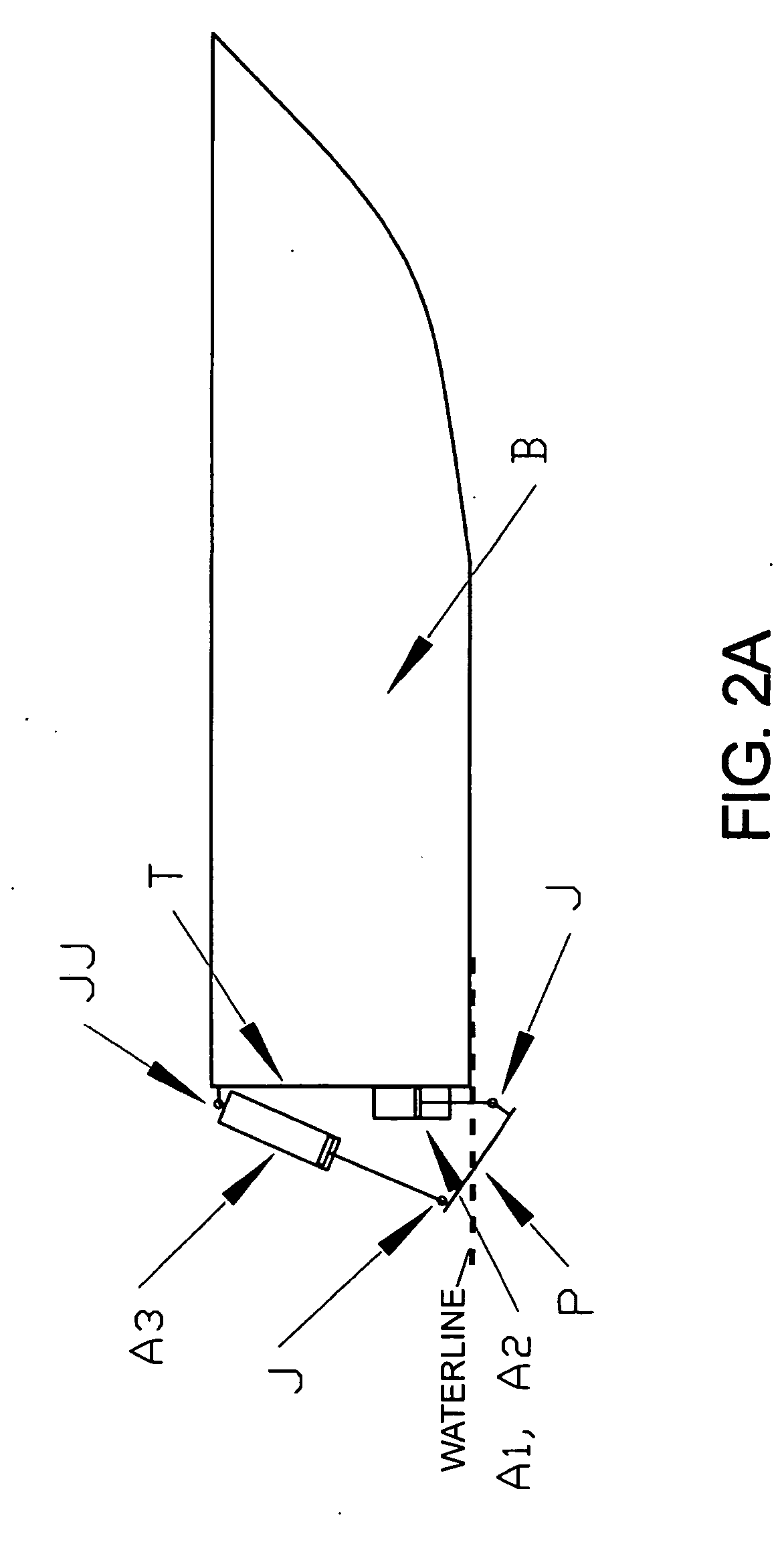
[0031] The preferred embodiment of the present invention is for boats that do not use an inboard-outboard or outboard engine and is depicted in FIG. 2A-FIG. 2D. The wake control plate “P” is connected to the transom “T” of the boat “B” by adjustable arms “A1”, “A2” and “A3”. Adjustable arms “A1” and “A2” are mounted rigidly on the Transom “T” and can only extend or contract vertically. “A1”, “A2” and “A3” are connected to wake control plate “P” with a non-rigid joint “J”, where a non-rigid joint is a connection that allows the arm 360 degrees of angular flexibility in one plane and up to approximately 20 degrees of angular flexibility in the direction perpendicular to that plane. (An example of a non-rigid joint that rotates 360 degrees in one direction and up to 20 in the other is the rubber gasket joint typically used on the bottom end of automobile shock absorbers). Non-rigid joints give the wake control plate the flexibility to tilt about any axis as the length of the adjustable...


PUM


Abstract

The present invention is a wake control mechanism for watercrafts comprising flat or upwardly curved wake control plate(s) which is / are connected to the stern in a variety of ways, either fixed or adjustable, such that the water passing beneath and / or beside the transom is scooped upward by the plate(s) and the watercraft is therefore pushed deeper into the water causing a larger wake. Additionally the plate(s) may have walls so that the scooped water is held above water level thus adding weight and further increasing wake size. Adjustments to the plate(s) position may be used to control the shape as well as the size of the wake.

Description

CROSS-REFERENCE TO RELATED APPLICATION [0001] Pursuant to 35 USC § 120, this application claims priority to and benefit of U.S. Utility patent application Ser. No. 10 / 734,888, filed Dec. 15, 2003, on behalf of inventor Steven Clay Moore, entitled “Wake Control Mechanism”.FIELD OF INVENTION [0002] The invention relates to a plate, typically behind a boat's transom to increase wake size, and / or modify wake shape. BACKGROUND [0003] Because wakeboarders like big wakes, boats built for wakeboarding usually now have water tanks, called bladders installed near the back of the boat to increase boat weight or “displacement” and thus increase wake size. Patents cover various bladder configurations. One patent covers a totally different method of modifying a boat wake by placing a flat plate (called a “trim tab′) at the bottom-center of the transom. This method can change the shape of the wake, but it is not intended or effective for increasing wake size, because trim tabs raise the back or “s...

Claims


Application Information

Patent Timeline
Patent Type & Authority Applications(United States)
IPC IPC(8): B63B1/22B63B39/06B63B59/02
CPCB63B39/061B63B1/22
Inventor MOORE, STEVEN CLAY
Owner MOORE STEVEN CLAY
Why Eureka
Try Eureka