
Medium voltage motor control center arc resistant enclosure

a technology of motor control center and enclosure, which is applied in the direction of substation/switching arrangement casing, furniture parts, sectional furniture, etc., to achieve the effects of reducing manufacturing steps, reducing heat rise, and reducing components

Inactive Publication Date: 2006-11-28
SQUARE D CO
View PDF17 Cites 38 Cited by
  • Summary
  • Abstract
  • Description
  • Claims
  • Application Information

AI Technical Summary

Benefits of technology

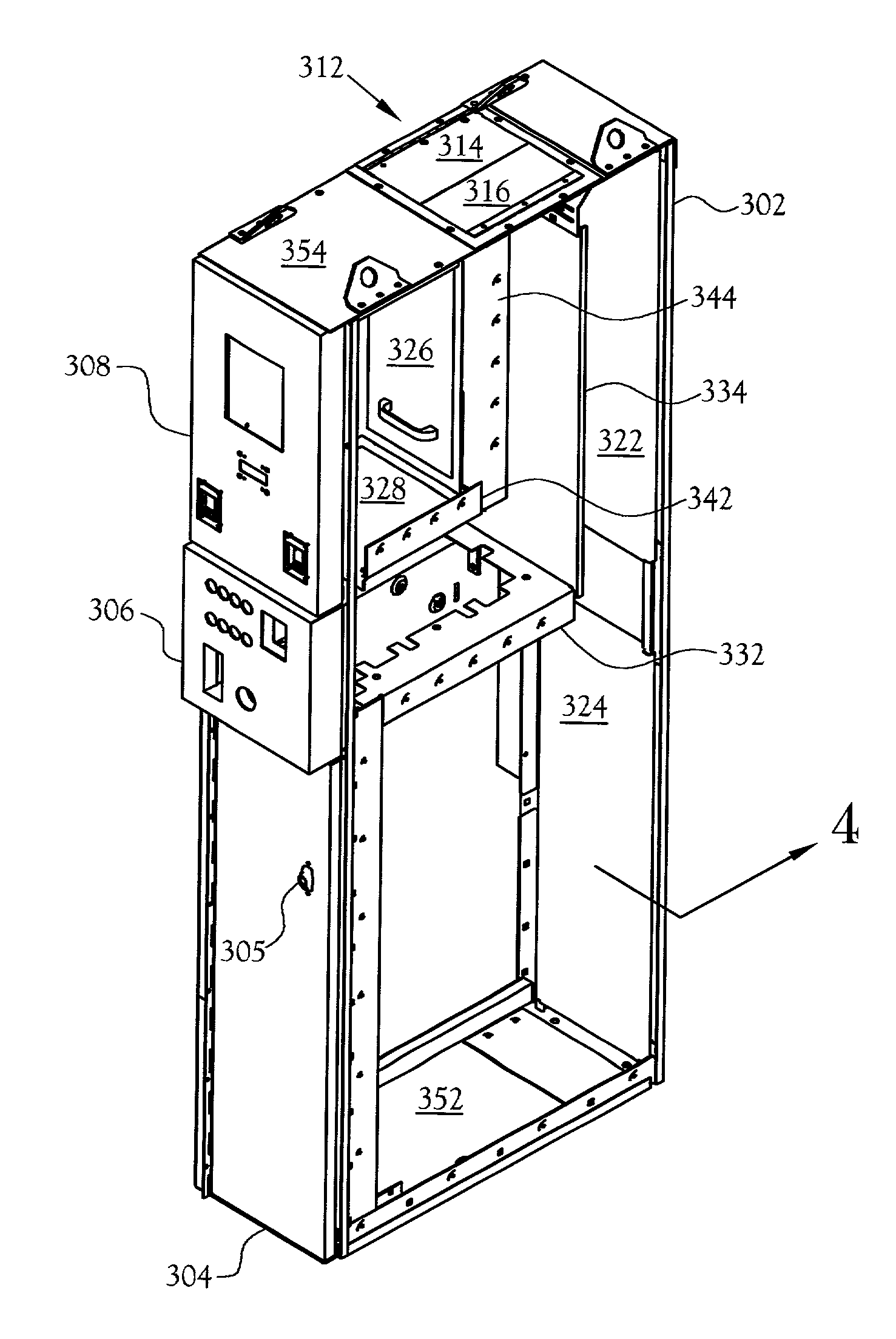
[0004]A medium voltage controller for electrical equipment, such as motors, transformers, reactors, and capacitors, is provided. The controller is a one-high unit, that is, a single contactor in a full-height cabinet, with the contactor mounted near the base of the controller, the fuses and grounding switch located near the vertical center, the disconnect switch mounted above the fuses, and the controller's instrument compartment located in the upper portion of the controller. The motor controller uses cast components to minimize components, fabrication steps, maintenance, and heat rise.
[0005]The motor controller is enclosed in an arc resistant cabinet, which uses the pressure generated by a fault to provide the sealing action to contain the fault forces. The rear, removable panels are inside the cabinet and engage lips surrounding the cabinet opening. Pressure inside the cabinet forces the panels against the inside surface of the cabinet and distributes the resulting load over a large area. The front access doors each have a continuous hinge and multiple latching tabs. The sheet metal panels of the cabinet are secured with a dimple-in-a-dimple feature, which provides strength and rigidity to the cabinet. At points where the panels are secured, each sheet metal part is formed with a dimple having a fastener hole in its center. The corresponding dimples in each sheet metal part are mated and fastened.
[0011]The fuses are mounted independently from the contactor assembly. The fuse spring clips are attached to a cast housing that provides corona protection and, in the case of the upper fuse clip housing, serves as the lower contact for the disconnect switch.
[0012]Each phase of the disconnect switch is formed of four conducting cast components. The cast upper switch contact includes a flat contact surface to which the main bus is connected. The cast lower switch contact includes the upper fuse clip housing. The cast configuration eliminates multiple connections, which are susceptible to high resistance and, consequently, heating. Electrical continuity between each of the two switch contacts is provided by two parallel plates that contact the two switch contacts by the disconnect switch operating mechanism. In the open position, the disconnect switch is earthed.

Problems solved by technology

Pressure inside the cabinet forces the panels against the inside surface of the cabinet and distributes the resulting load over a large area.

Method used


Image

  • Medium voltage motor control center arc resistant enclosure
  • Medium voltage motor control center arc resistant enclosure
  • Medium voltage motor control center arc resistant enclosure

Examples


Embodiment Construction

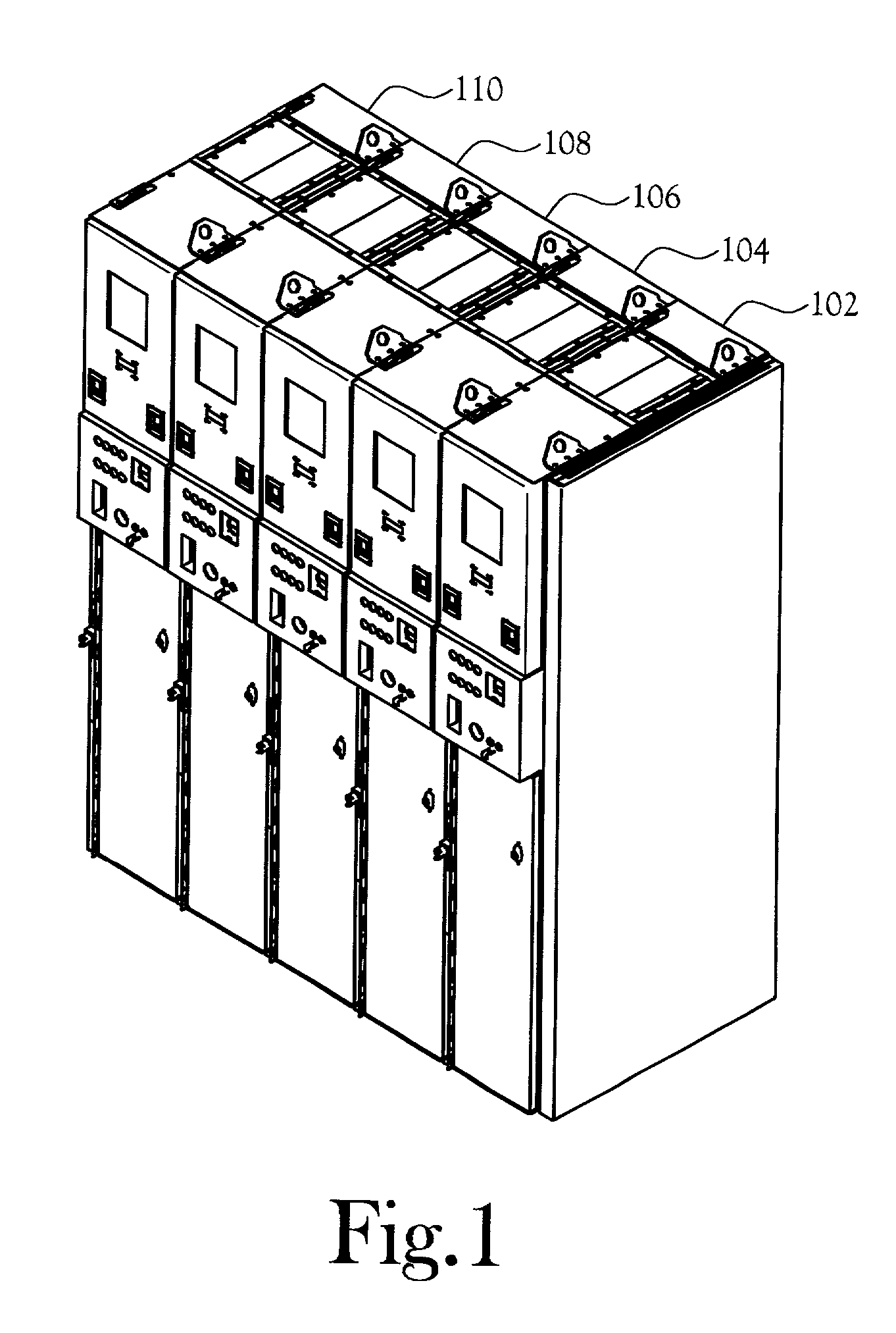
[0054]An apparatus for controlling medium voltage electrical equipment, such as motors, transformers, reactors, and capacitors, is disclosed. The apparatus, illustrated in FIG. 1 in a five-wide configuration, is a medium voltage motor controller 102, 104, 106, 108, and 110.

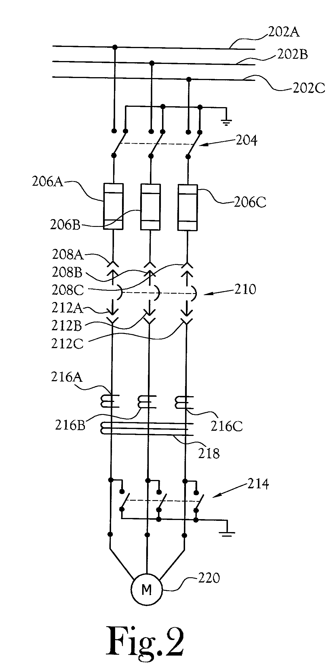
[0055]FIG. 2 is a schematic diagram of the controller 102. A three-phase bus 202 connects to a disconnect switch 204, which is connected to a set of fuses 206A, 206B, and 206C. Although the schematic shows one fuse 206 per phase, those skilled in the art will recognize that the physical configuration can include multiple fuses per phase in order to satisfy current carrying and current interrupting requirements. The contactor 210 is connected to the fuses 206 and load 220 through draw-out stabs and connectors 208 and 212. Between the stabs and connectors 212 and the driven motor M or load 220 are a load discharge device 214 and current transformers 216 and 218. The illustrated embodiment controls a motor M load. Th...


PUM


Abstract

A medium voltage controller for electrical equipment, such as motors, transformers, reactors, and capacitors, having an arc resistant cabinet, swaged internal electrical connections, a one-piece self-aligning withdrawable finger cluster, a pull-out instrument compartment, a load discharge device, cast fuse holders, disconnect switch, a switch illuminator, low power current transformers, and an optical temperature measuring system. The arc resistant cabinet relies on the pressure generated by an arc fault to provide the sealing action to contain the fault forces. The cabinet's rear panels are inside the cabinet and the panel lips mate to edges of the cabinet opening. The front doors each have a series of latching tabs along one side and a hinge along the opposing side. A dimple-in-a-dimple joint provides shear strength for panel joints. At the top of the cabinet is an exhaust vent.

Description

CROSS-REFERENCE TO RELATED APPLICATIONS[0001]Not ApplicableSTATEMENT REGARDING FEDERALLY SPONSORED RESEARCH OR DEVELOPMENT[0002]Not ApplicableBACKGROUND OF THE INVENTIONField of Invention[0003]This invention pertains to an enclosure for a medium voltage motor controller. More particularly, this invention pertains to an enclosure that is arc resistant.BRIEF SUMMARY OF THE INVENTION[0004]A medium voltage controller for electrical equipment, such as motors, transformers, reactors, and capacitors, is provided. The controller is a one-high unit, that is, a single contactor in a full-height cabinet, with the contactor mounted near the base of the controller, the fuses and grounding switch located near the vertical center, the disconnect switch mounted above the fuses, and the controller's instrument compartment located in the upper portion of the controller. The motor controller uses cast components to minimize components, fabrication steps, maintenance, and heat rise.[0005]The motor cont...

Claims


Application Information

Patent Timeline
Patent Type & Authority Patents(United States)
IPC IPC(8): A47B53/00H01H9/16H01H31/12H02B1/28
CPCH01H31/12H02B1/28H02B13/025H01H9/16H01H2009/0292
Inventor BYRON, ELDRIDGE R.MOTLEY, GREGORY O.GROFF, MARY B.
Owner SQUARE D CO
Learn More