Integrated air supply with humidification control for fuel cell power systems

a fuel cell power system and air supply technology, applied in the field of manipulating airflow, can solve the problems of reducing the hydration level of the membrane, limiting the electrical conductivity of the membrane, and no guarantee of local water balance, so as to reduce the number of components, reduce the complexity of the concomitant device, and reduce the loss of individual or similar dedicated conduits

Inactive Publication Date: 2009-09-22
GM GLOBAL TECH OPERATIONS LLC
View PDF9 Cites 7 Cited by
  • Summary
  • Abstract
  • Description
  • Claims
  • Application Information

AI Technical Summary

Benefits of technology

[0006]These needs are met by the present invention, wherein a fuel cell system and a method of operating the system that incorporates the features discussed below is disclosed. In accordance with a first aspect of the present invention, a device including an electrochemical conversion assembly, an oxidant delivery assembly and a controller is disclosed. The electrochemical conversion assembly is configured to combine an oxidant and a reductant, while the oxidant delivery assembly is fluidly coupled to the electrochemical conversion assembly. The controller is configured to operate the oxidant delivery assembly, which includes a compressor, heat exchanger, water vapor transfer unit and housing. The oxidant delivery assembly can be used to manipulate at least one property of the oxidant delivered from an oxidant source to make the oxidant more suitable for use in the electrochemical conversion assembly. The oxidant delivery assembly's housing defines a chamber therein. The compressor can be used to pressurize the chamber with oxidant from the oxidant source, while the heat exchanger is positioned within the chamber and can be used to transfer heat from oxidant within the chamber to an exhaust fluid produced by the electrochemical conversion assembly. The water vapor transfer unit is positioned within the chamber and can be used to transfer water vapor from the aforementioned exhaust fluid to the pressurized oxidant in the chamber. It will be appreciated that the one or more elements positioned within the housing may share exterior surfaces with the housing, or even define exterior housing surfaces; the intent is to have a common housing that is able to provide simple packaging for the disparate components to minimize space, component redundancy and concomitant device complexity. In addition, by utilizing a common housing, pressure losses to the oxidant being conveyed to the electrochemical conversion assembly can be minimized, as losses associated with narrow, individual or similarly dedicated conduit can be reduced. In the present context, terms such as “oxidant source” and its variants are to be understood broadly, encompassing any device, container or environment (including the ambient environment) configured to provide an oxidant-bearing fluid, such as air, oxygen or related compound, mixture or the like.
[0009]The water vapor transfer unit may include a porous medium made up of numerous microtubes through which water vapor or related humidity-increasing fluids may flow. The porous nature of the microtubes promotes diffusion of moisture from a moisture-bearing fluid (such as the exhaust fluid from a fuel cell cathode) into the oxidant in the chamber to increase the humidity of the supply oxidant being introduced into the electrochemical conversion assembly. Condensate from the saturated exhaust fluid can form on the inner wall of these microtubes, and can subsequently diffuse across the membrane walls of each tube. The heat exchanger is used to reduce the temperature of the oxidant exiting the compressor while increasing the temperature of the exhaust fluid flowing through the porous microtubes. This is beneficial in that the otherwise waste heat produced in the oxidant during its compression can be used to raise the temperature of the water-rich fluid that is passing through the microtubes; by raising the temperature of fluid flowing from the fuel cell exhaust (i.e., stack offgas), the likelihood of water being in a vapor form that can more readily be introduced into the oxidant flowing through the chamber is enhanced, which in turn can be used to increase hydration within parts of the fuel cell that may otherwise dry out during operation. Furthermore, decreased oxidant temperature relative to stack offgas temperature increases the water transfer driving force, and hence efficiency, across the water vapor transfer membrane. Accordingly, during system operation, the heat exchanger can be used to maintain the temperature of the exhaust fluid entering the porous microtubes closer to (although, preferably not in excess of) approximately one hundred degrees Celsius. As is common in heat exchangers, the present heat exchanger may define at least two flowpaths that are in thermal communication with one another. The flowpaths may include a first flowpath configured to be fluidly disposed between the oxidant source and a fuel cell cathode inlet; and a second flowpath configured to be fluidly coupled to a fuel cell cathode outlet. In a more particular embodiment, the water vapor transfer unit and the heat exchanger are fluidly adjacent one another. In addition, the water vapor transfer unit and the heat exchanger can be fluidly coupled to a fuel cell cathode outlet. This is advantageous in that it economizes on space in volume-limited applications, as the heat exchanger and water vapor transfer unit both utilize reactant byproducts from the cathode to manipulate the air yet to be introduced to the cathode as reactant. For example, they can both be fluidly coupled to a fuel cell cathode outlet. At least one baffle may be disposed in the chamber downstream of the compressor. The use of baffles helps to ensure more even distribution of air properties.
[0013]Optionally, the properties that can be modified by the fuel delivery device include air pressure, air temperature, relative humidity, mass flow or particulate concentration. By way of example, when a compressor (such as previously described) operates on the air, both the temperature and pressure of the air that passes through the chamber defined inside the housing (both similar to that discussed in conjunction with the previous aspect) will be increased. The heat exchanger can be operated to increase the temperature of the exhaust fluid formed during the operation of the fuel cell by absorbing some of the excess heat in the compressed air. The simultaneous increase in exhaust fluid temperature and the decrease in microtube wall temperature (the latter enabled by contact with the lower temperature compressed air that has passed through the heat exchanger) promotes the condensation, subsequent migration and reevaporation of water into a fluid path coupling the air delivery device to the fuel cell, thereby increasing the humidity of supply air entering the fuel cell. Operating the heat exchanger ensures temperatures adequate to increase the amount of vapor present in the moisture-bearing exhaust fluid, thereby improving the humidity in the chamber. With water vapor, increasing the temperature of the exhaust fluid to closer to one hundred degrees Celsius is consistent with such objectives. In addition, a filter may be placed in a flowpath defined in the air delivery to reduce particulate contamination of the air. As with the previous aspect, at least one attenuator can be connected to the air delivery device to reduce the noise associated with the flowing of air into the fluid delivery device.

Problems solved by technology

Contrarily, too little hydration limits electrical conductivity of the membrane.
Exacerbating the difficulty in maintaining a balance in water level is that there are numerous conflicting reactions taking place in a fuel cell that are simultaneously increasing and decreasing its hydration levels.
Furthermore, many of these effects are localized such that even if global levels of hydration are maintained in the fuel cell, there is no guarantee that local water balance is maintained.
Of course, the use of humidification, temperature, pressure and mass flow control devices necessitates additional fuel cell system weight, size and complexity (in, for example, the form of pumps coupled to intricate valve networks tied together with precision control mechanisms), as well as reductions in fuel cell output or efficiency in situations where such componentry requires a source of power to operate.
Such disadvantages are especially troublesome for vehicle-based fuel cell applications, as the often redundant componentry would take up precious vehicle space otherwise used for passenger, comfort or safety features.

Method used


Image

  • Integrated air supply with humidification control for fuel cell power systems
  • Integrated air supply with humidification control for fuel cell power systems
  • Integrated air supply with humidification control for fuel cell power systems

Examples


Embodiment Construction

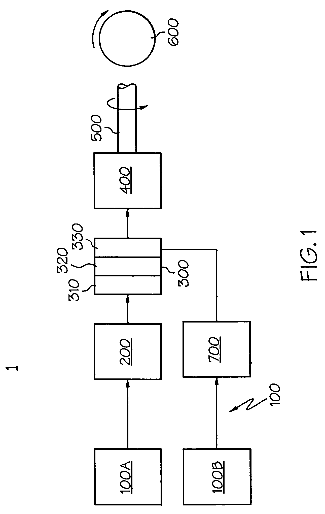
[0024]Referring initially to FIGS. 1 and 4, a block diagram highlights the major components of a mobile fuel cell system 1 according to the present invention, as well as a representative placement of a fuel cell system into an automotive application. Referring with particularity to FIG. 1, the system 1 includes a fuel delivery system 100 (made up of fuel source 100A and oxygen source 100B), fuel processing system 200, fuel cell 300, one or more energy storage devices 400, a drivetrain 500 and one or more motive devices 600, shown notionally as a wheel. While the present system 1 is shown for mobile (such as vehicular) applications, it will be appreciated by those skilled in the art that the use of the fuel cell 300 and its ancillary equipment is equally applicable to stationary applications. It will also be appreciated by those skilled in the art that other fuel delivery and fuel processing systems are available. For example, there could be, in addition to a fuel source 100A and oxy...


PUM

PropertyMeasurementUnit
temperatureaaaaaaaaaa

Abstract

A fluid delivery device for an electrochemical conversion assembly. In one embodiment, the electrochemical conversion assembly is a fuel cell system. The device includes one or more fluid-manipulating components combined into a housing to minimize weight, size and complexity. In one form, the device may include a compressor, heat exchanger and a water vapor transfer unit, at least the latter two of which are located within a chamber defined by the housing. A controller can be used to monitor and selectively vary the extent to which at least one of these components modifies properties a fluid (such as air) that can be used as a reactant in the electrochemical conversion assembly. In a particular form, the heat exchanger and water vapor transfer unit can cooperate to promote the hydration of the reactant.

Description

BACKGROUND OF THE INVENTION[0001]The present invention relates generally to manipulating airflow for use as a reactant in a fuel cell system, and more particularly to integrating air supply system components in such a way as to reduce the size, weight and complexity associated with such airflow manipulation.[0002]While conventional power source devices (such as internal combustion engines, including piston and gas turbine-based platforms) are well-known as ways to produce, among other things, motive, heat and electric power, recent concerns about the effects they and their fuel sources have on the environment have led to the development of alternative means of producing such power. The interest in fuel cells is in response to these and other concerns. One form of fuel cell, called the proton exchange membrane (PEM) fuel cell, has shown particular promise for vehicular and related mobile applications, using hydrogen and oxygen as the primary reactants to produce electricity with wate...

Claims


Application Information

Patent Timeline
Patent Type & Authority Patents(United States)
IPC IPC(8): H01M8/04H01M8/00H01M8/10
CPCH01M8/04149H01M8/04029H01M8/04089Y02T90/32H01M2250/20Y02E60/50H01M8/0662Y02T90/40
Inventor MELTSER, MARK A.JARRAH, YOUSEF M.JAMES, RONALD L.KONIG, CHRISTIANRUHL, JOHN B.
Owner GM GLOBAL TECH OPERATIONS LLC
Why Eureka
Try Eureka