Suspension isolator equalizer
a technology of isolator and suspension, which is applied in the direction of spring/damper, mechanical apparatus, transportation and packaging, etc., can solve the problems of translating road shock and vibration, and achieve the effect of reducing vibration, reducing vibration, and reducing vibration
- Summary
- Abstract
- Description
- Claims
- Application Information
AI Technical Summary
Benefits of technology
Problems solved by technology
Method used
Image
Examples
first embodiment
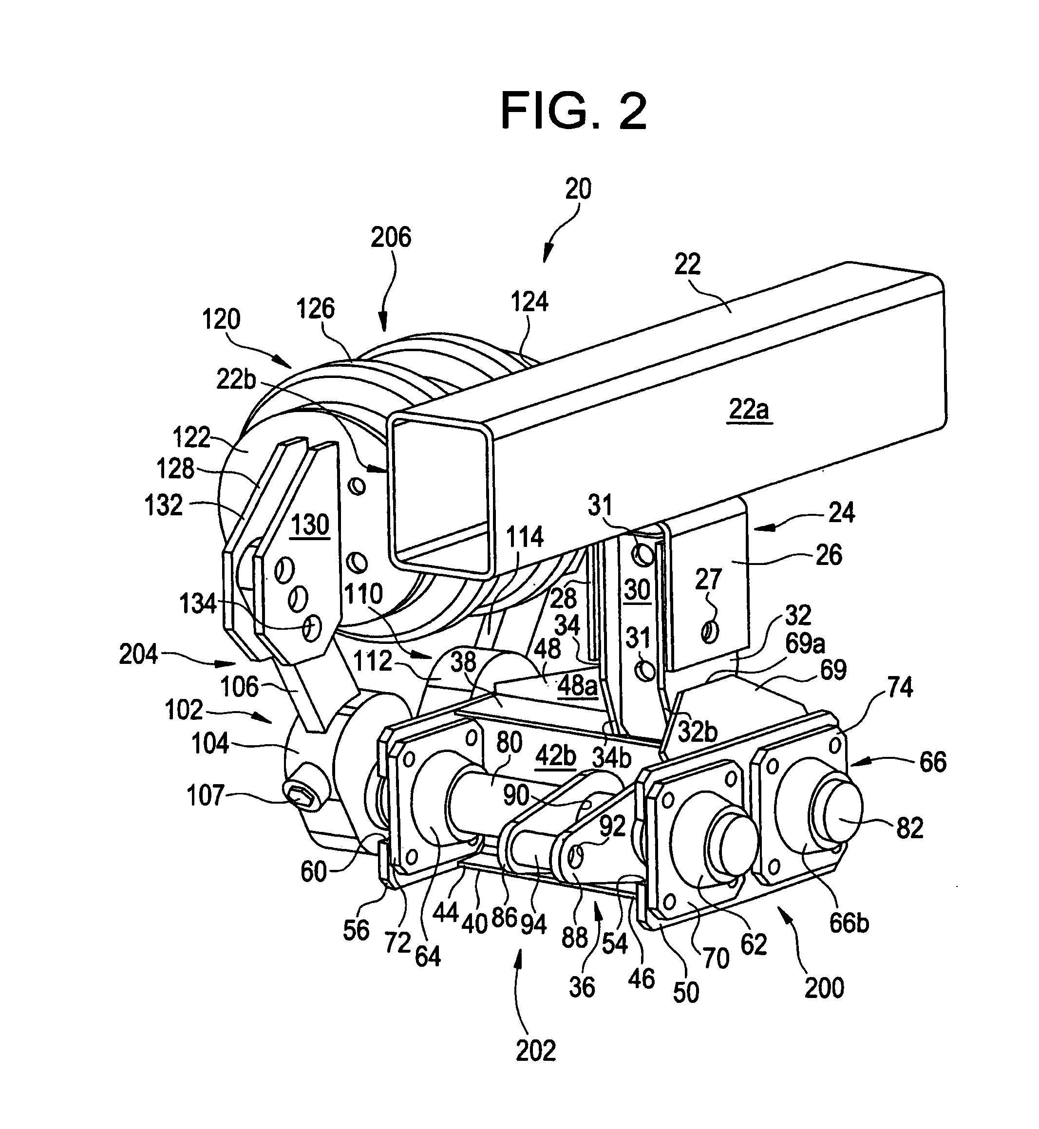
[0037]Attention is invited to the first embodiment shown in FIGS. 2–10. As shown in FIG. 2, a suspension system 20 in accordance with the present invention is attached to the frame 22 (a portion of which is shown) of a vehicle, such as a trailer or a tractor. It is to be understood that the suspension system 20 includes identical left and right sides to be used on the left and right sides of the vehicle, however only one side of the suspension system 20 is shown in the drawings and described herein. The suspension system 20 is used to absorb shocks and vibrations encountered by the wheels of the vehicle.
[0038]The frame 22 generally extends along the length of the vehicle. The frame 22 includes an outer surface 22a and an inner surface 22b. For purposes of this description, directions are defined in the following manner: forward / front refers to the direction toward the front of the vehicle, rearward / rear refers to the direction toward the back of the vehicle, inward / inner refers to t...
second embodiment
[0088]Attention is invited to the invention shown in FIGS. 11–14. As shown in FIG. 11, the suspension isolator 300 includes a frame bracket 302 for mounting the isolator 300 to the frame (not shown) of the vehicle. The frame bracket 302 attaches to the center frame hanger of the vehicle by suitable means. The frame bracket 302 includes a first bracket attachment 304, a second bracket attachment 306, a front plate 303 and a rear plate 305. The first and second bracket attachments 304, 306 extend between the front and rear plates 303, 305 and are generally perpendicular thereto. The first and second bracket which extend downwardly from the frame of the vehicle by suitable means.
[0089]The first bracket attachment 304 is preferably metal. The first bracket attachment 304 is elongated and includes a first end 304a and a second tapered end 304b. The first end 304a of the bracket is positioned proximate the frame of the vehicle.
[0090]The second bracket attachment 306 is also metal and is s...
third embodiment
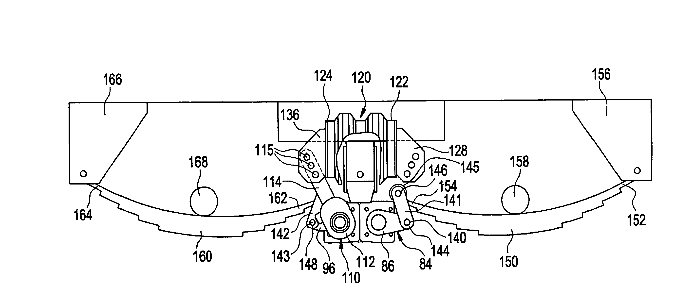
[0113]Attention is invited to the isolator 500 shown in FIGS. 15–18. Unlike the isolators 20 and 300 described above, the isolator 500 does not include slack adjusters for adjusting the ride height.
[0114]The isolator 500 includes a frame bracket 502 for attaching the isolator 500 to the frame of the vehicle. The frame bracket 502 includes a first bracket attachment 504, a second bracket attachment 506, a front plate 503 and a rear plate 505. A first bracket attachment 504 is positioned at the outer end of the frame bracket 502 and a second bracket attachment 506 is positioned at the inner end of the frame bracket 502. The front plate 503 extends between the first and second bracket attachments 504, 506 and is generally perpendicular thereto. The rear plate 505 extends between the first and second bracket attachments 504, 506 and is generally perpendicular thereto.
[0115]The first bracket attachment 504 is preferably metal. The first bracket attachment 504 is elongated and includes a ...
PUM
 Abstract
Description
Claims
Application Information
 - R&D
- Intellectual Property
- Life Sciences
- Materials
- Tech Scout
- Unparalleled Data Quality
- Higher Quality Content
- 60% Fewer Hallucinations
Browse by: Latest US Patents, China's latest patents, Technical Efficacy Thesaurus, Application Domain, Technology Topic, Popular Technical Reports.
© 2025 PatSnap. All rights reserved.Legal|Privacy policy|Modern Slavery Act Transparency Statement|Sitemap|About US| Contact US: help@patsnap.com


