Card edge connector

a card edge and connector technology, applied in the direction of electrical equipment, coupling device connection, support structure mounting, etc., can solve the problems of seized retention wing of the hold-down device, failure to be assembled, and overlong entire hold-down devi

Active Publication Date: 2019-06-27
MOLEX INC
View PDF20 Cites 4 Cited by
  • Summary
  • Abstract
  • Description
  • Claims
  • Application Information

AI Technical Summary

Benefits of technology

[0014]The present disclosure at least has the following beneficial effects: the non-destructive limit abutment structure between the latching elastic arm integrally formed on both sides of the mounting section of the board fastener and the insulative housing enables the board fastener to be assembled more robustly and firmly on the insulative housing, particularly is capable of withstanding mechanical shock and vibration. Moreover, a limiting structure formed directly by the latching elastic arm which can be limited in position by the insulative housing in the mating direction enables the dimension of the board fastener to be effectively compact.

Problems solved by technology

However, such a structure of the locking tab is easily cracked at the position where the locking tab is torn to reduce the strength of the entire locking clip, and the locking tab is short and hard, and is easy to wipe a hole wall surface of the insulative housing to cause harmful interference during assembling, which cause that it not easy to assemble.
However, such a configuration must more accurately control the distance between the tip of the stop and the top edge of the retention wing, and an insertion force must be accurately controlled, otherwise, the retention wing of the hold-down device cannot be elastically displaced toward the lower surface of the shoulder, which may result in that the retention wing of the hold-down device is seized and fails to be assembled.
Moreover, the stop and the retention wing are arranged in an up-down direction and have a certain distance therebetween, so that the entire hold-down device is overlong, and is not applicable to some space-limited or compact electrical connectors.

Method used


Image

  • Card edge connector
  • Card edge connector
  • Card edge connector

Examples


Embodiment Construction

[0070]Before the present disclosure is described in detail, it should be noted that like elements are indicated by same reference numerals in the following description.

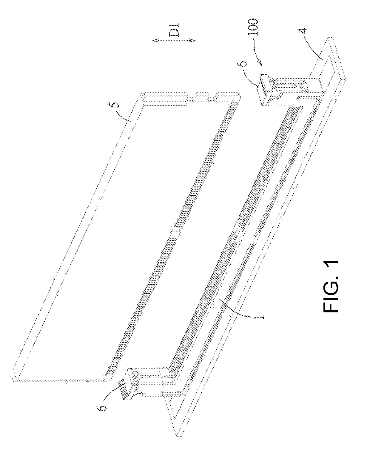
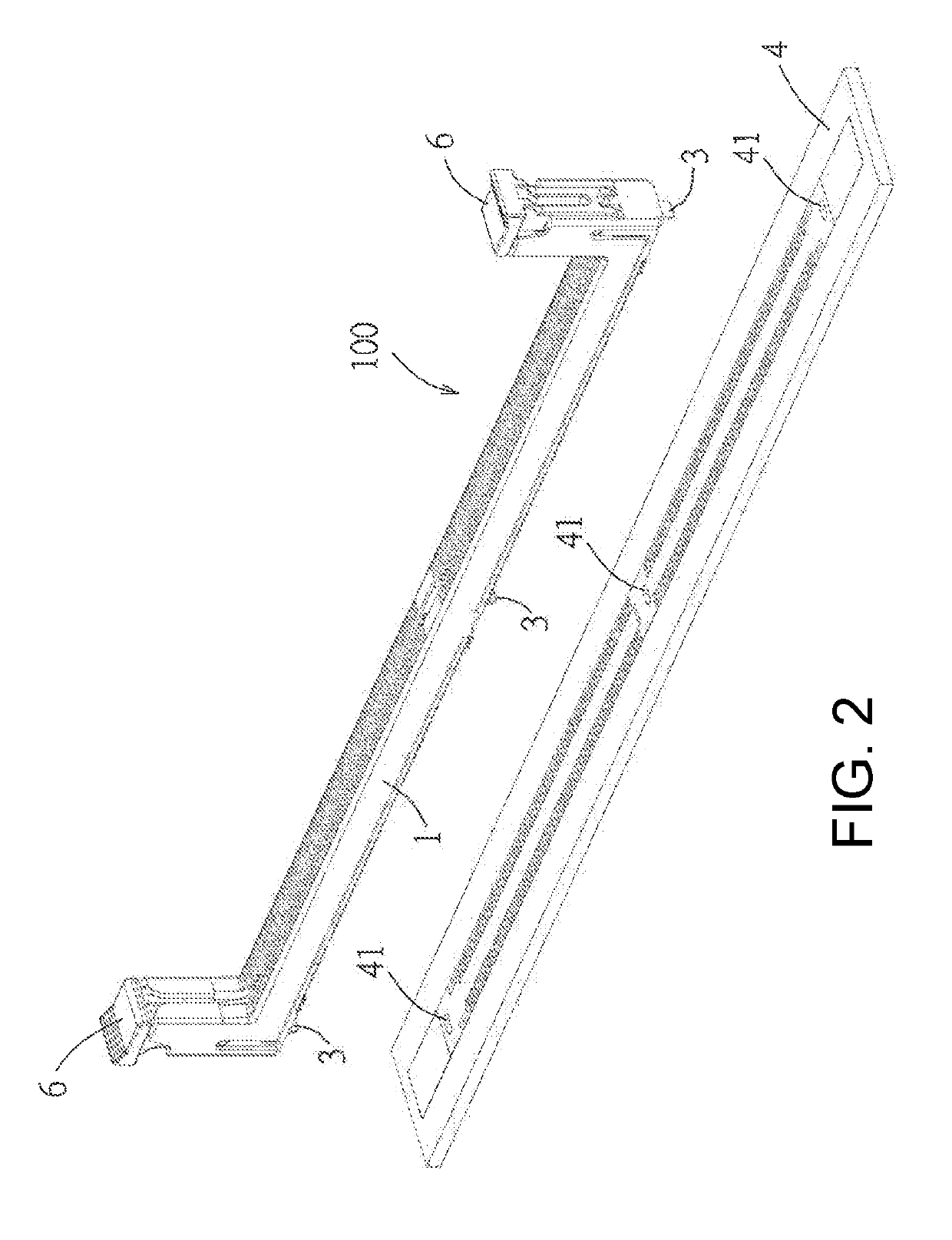
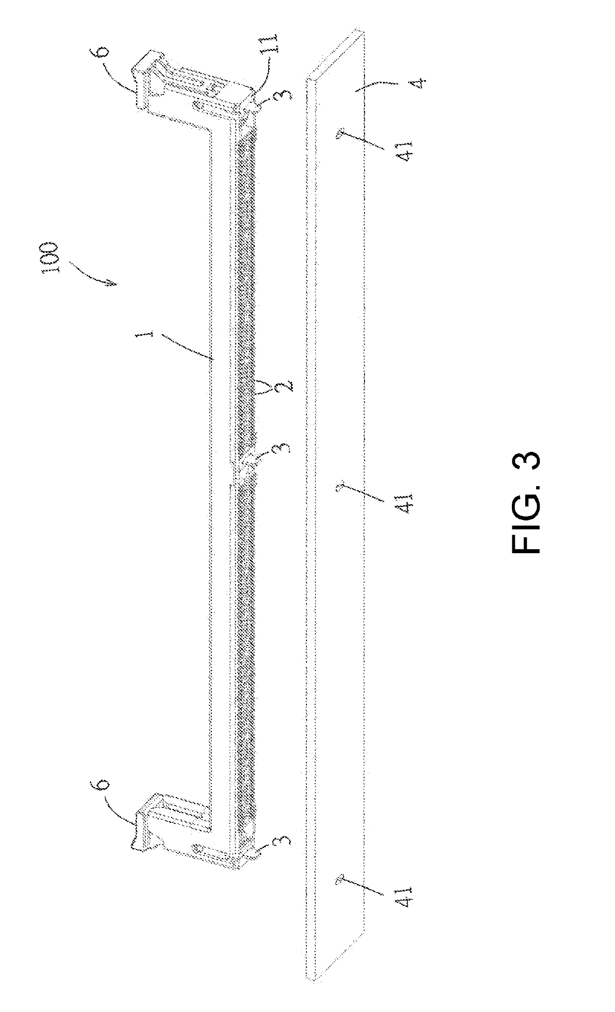
[0071]Referring to FIG. 1 to FIG. 3, a first embodiment of an electrical connector of the present disclosure is adapted to be mounted on a circuit board 4 to electrically connect an electronic card 5. The electrical connector 100 comprises an insulative housing 1, a plurality of conductive terminals 2 provided to the insulative housing 1 and a plurality of board fasteners 3 provided to the insulative housing 1. In the first embodiment, the electrical connector 100 is a card edge connector, and further comprises two latching members 6 respectively pivoted to both ends of the insulative housing 1 to latch with and fix the electronic card 5 when the electronic card 5 is mated with the electrical connector 100. The plurality of board fasteners 3 are used to be provided through the corresponding through hole 41 on the circ...


PUM


Abstract

The present disclosure provides an electrical connector. The electrical connector comprises an insulative housing, a plurality of conductive terminals and a board fastener. The insulative housing has a mounting surface and a mating surface on opposite sides in a mating direction and a mounting chamber. The mounting chamber has a top accommodating portion and a bottom accommodating portion extending and penetrating the mounting surface from the top accommodating portion in the mating direction, two side walls defining the mounting chamber each are formed with a top limiting surface and a bottom limiting surface which define the top accommodating portion. The fastener has a mounting section accommodated in the top accommodating portion, an intermediate section extending from the mounting section and accommodated in the bottom accommodating portion and a tail section extending out of the mounting surface of the insulative housing from the intermediate section.

Description

RELATED APPLICATIONS[0001]This application claims priority to Chinese Application No. 201711350138.4, filed Dec. 15, 2017, which is incorporated herein by reference in its entirety.FIELD AND BACKGROUND OF THE PRESENT DISCLOSURE[0002]The present disclosure relates to an electrical connector, especially to an electrical connector having a board fastener to be fixed to a circuit board. Some existing electrical connectors need to be fixed with a circuit board through a locking clip fixed to an insulative housing. For example, U.S. Pat. No. 5,269,694 discloses an electrical connector that is fixed to a circuit board using a locking clip. The locking clip is substantially formed by stamping a metal plate and has two locking tabs formed by tearing and bending toward one plate surface of plate surfaces of a plate body and protruding from the one plate surface, and is fixed to an insulative housing through the locking tabs. However, such a structure of the locking tab is easily cracked at th...

Claims


Application Information

Patent Timeline
Patent Type & Authority Applications(United States)
IPC IPC(8): H01R12/70H01R12/72H01R13/627H05K7/14
CPCH01R12/7011H01R12/721H01R13/6273H05K7/1417H01R12/7064H01R12/716H01R12/737
Inventor SOH, ENG KAN
Owner MOLEX INC
Why Eureka
Try Eureka