Rotor supporting structure of windmill for power generation

a technology of supporting structure and windmill, which is applied in the direction of wind energy generation, machine/engine, renewable energy generation, etc., can solve the problems of reducing the load of the roller bearing retaining the rotor assembly and reducing the rolling resistance, so as to achieve easy jumboization, reduce the load, and increase the torque

Inactive Publication Date: 2006-12-05
KINPARA SHIRO
View PDF7 Cites 43 Cited by
  • Summary
  • Abstract
  • Description
  • Claims
  • Application Information

AI Technical Summary

Benefits of technology

[0006]The windmill of this invention, each longitudinal blade is mounted through the intermediary of the support, the longitudinal blade is located away from the rotation axis yielding a large torque. Further, since the longitudinal blade and the boss are jointed by plural supports, the winds cause few effects against the parts of the windmill except for the longitudinal blades. Further, its weight is light allowing easy jumboizing and enlarging of the power generation capacity.
[0007]In the case that the support is so composed as to yield a lift force in the direction of rotation when the longitudinal blades rotate in a wind, the rotating transversal blades mounted on the bosses so as to rotate horizontally yield a lift force bracing the rotor upward, which reduces the load of the roller bearing retaining the rotor assembly and reduces the rolling resistance. Accordingly, the high rotation efficiency and the large generated power can be easily obtained. In the case that the lift force exceeds the rotor assembly weight, the rotor assembly floats and further enhances the rotation efficiency.
[0008]In the case that the frame assembly is provided with a lock means to keep the longitudinal blade in a restrained condition at the position adjacent to the zone in which the longitudinal blades rotate, the longitudinal blades can be fixed by the lock means preventing the windmill or generator from failure due to hard rotation in a strong wind. Further, the direct fixing of the longitudinal blades prevents a large force to be applied to the support.
[0009]In the windmill of this invention, the frame assembly is provided with a ring placed horizontally at the position adjacent to the zone in which the longitudinal blades rotate, and the rotor assembly is provided with a wheel running along the ring, the load to the roller bearing supporting the rotor assembly is reduced and the rolling resistance is decreased. Accordingly, it has high rotation efficiency and large power generation capacity. Further, providing wheels on the longitudinal blade helps support the weight of the longitudinal blades removing loads from the radial supports.
[0010]In the case that wheels are mounted on the rotor assembly provided with the transversal blades, when the rotation speed of the rotor assembly is low the weight of the rotor assembly is supported by the wheel before it floats by the lift force yielded of the transversal blades. When the rotation speed of the rotor becomes high, it floats and the rolling resistance due to the wheel becomes zero. Therefore, the multiplier action of the transversal blades and the wheel achieves the stable rotation and efficient rotation together.

Problems solved by technology

In the case that the support is so composed as to yield a lift force in the direction of rotation when the longitudinal blades rotate in a wind, the rotating transversal blades mounted on the bosses so as to rotate horizontally yield a lift force bracing the rotor upward, which reduces the load of the roller bearing retaining the rotor assembly and reduces the rolling resistance.

Method used


Image

  • Rotor supporting structure of windmill for power generation
  • Rotor supporting structure of windmill for power generation
  • Rotor supporting structure of windmill for power generation

Examples


Embodiment Construction

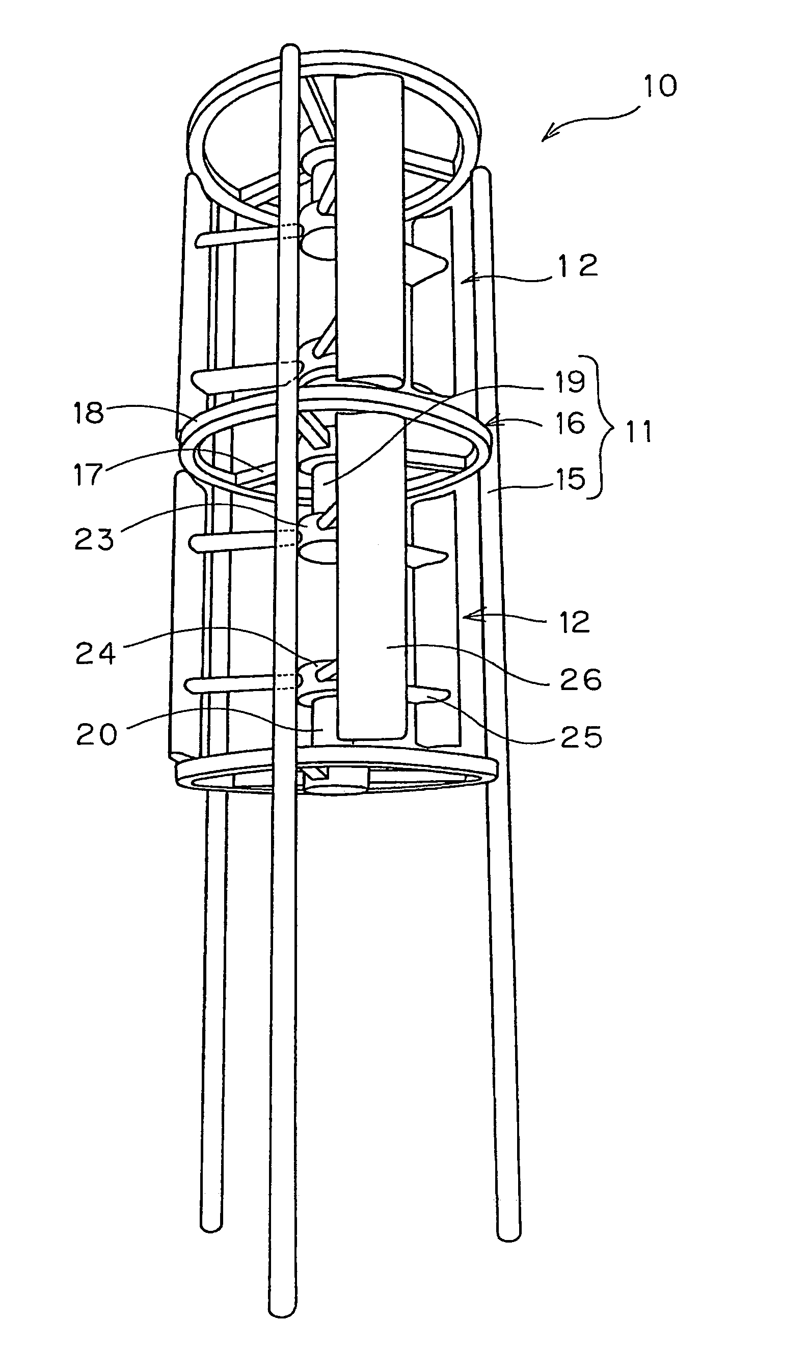
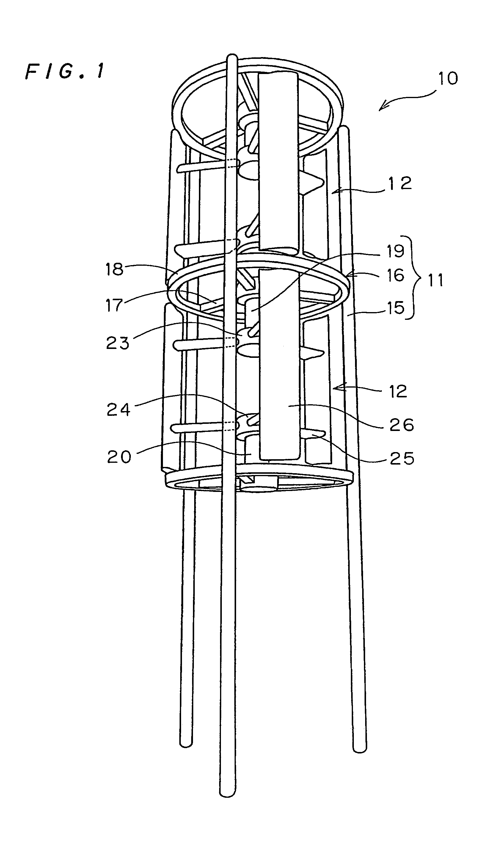
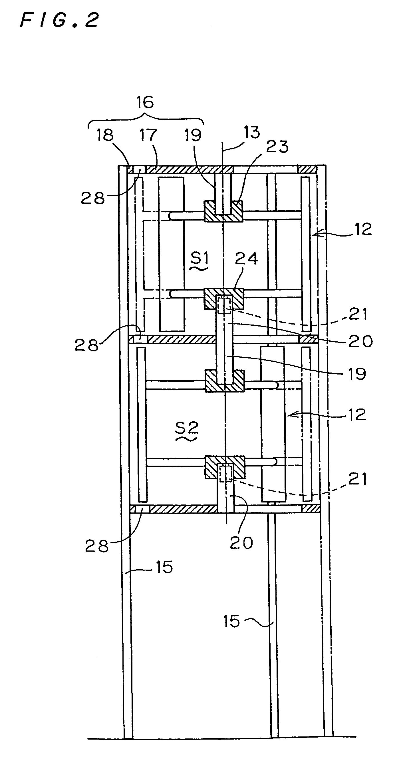
[0021]The windmill 10 shown in FIG. 1 is composed of the frame 11 and the rotors 12 located on the upper stage and the lower stage in the frame. The each rotor 12 is, as shown in FIG. 2, provided rotatively around the vertical axis 13 of the frame 11.

[0022]The frame 11 comprises three vertical legs 15 and joint part 16 connecting these legs in an equal interval circumferentially, as shown in FIG. 3. The joint parts 16 are located in three stages, at the top of the leg 15, at the position upper than the lower end to some extent, and at the medium position of them. In the space S1, S2 between each joint part 16, the rotors 12 are accommodated (See FIG. 2). The joint part 16 comprises three spoke 17 extending radially and the ring 18 to connect the outer edge of the spoke 17 to each other. On the center of the spoke 17 of the upper joint part 16, the cylindrical bearing 19 for supporting the rotor rotatively is mounted downward. Further, on the joint part 16 the bearing 20 is mounted u...


PUM


Abstract

A windmill 10 includes a frame 11 and a rotor 12 provided rotatively around the vertical shaft center. The rotor includes bosses 23, 24 located above and below, plural transversal blades 25 extending radially from the bosses, longitudinal blades 26 held by the front edges of the transversal blades 25 of both above and below bosses. The frame includes bearing 19, 20 supporting the bosses 23, 24 of the rotor rotatively around the vertical shaft center, spokes 17 provided radially supporting the bearing, and legs 15 holding the spoke 17 away from the ground. In the lower bearing 20, a generator connected to the boss 24 of the rotor 12 is accommodated.

Description

FIELD OF THE INVENTION[0001]This invention relates to a windmill for wind power generation, and more particularly to a large windmill having large power generation capacity.BACKGROUND ARTS[0002]As a windmill for wind power generation, such a type of windmill is known that it has a horizontal rotation axis rotatively on the top of a supporting post, and the front edge of the rotation axis is provided with plural blades of a propeller shape. The other type of windmill is also known that it has a vertical rotation axis provided with plural longitudinal blades of a radial shape. These types of windmill have high power generation efficiency when they are jumboized because they receive a larger wind force.[0003]However, merely jomboizing makes it difficult to support its own weight, and the own weight increases rotational resistance causing difficulties in practical application. Accordingly, conventional windmills have a limit of the power generation capacity up to 3000 kw. This invention...

Claims


Application Information

Patent Timeline
Patent Type & Authority Patents(United States)
IPC IPC(8): F03D3/02F03D3/00
CPCF03D3/005F03D3/02F05B2240/214F05B2240/40Y02E10/74Y10S415/907F03D13/10F03D13/20Y02E10/728F03D3/00
Inventor KINPARA, SHIROUCHIYAMA, HISAKAZU
Owner KINPARA SHIRO
Why Eureka
Try Eureka