Hinged electrical connector for insulated cable

a technology of insulated cable and electrical connector, which is applied in the direction of coupling device connection, contact member penetrating/cutting insulation/cable strand, electrical apparatus, etc., can solve the problem of difficult and reliable connection of separate ground wires contained in cables, severe limitations of devices, etc., and achieve the effect of efficient electrical connection

Active Publication Date: 2006-12-05
ASLAN INDS
View PDF27 Cites 31 Cited by
  • Summary
  • Abstract
  • Description
  • Claims
  • Application Information

AI Technical Summary

Benefits of technology

[0010]It is an object of the present invention to provide a connector with a cavity sized to receive an unstripped end of an electrical cable and which efficiently makes an electrical connection between a hot, neutral and ground wire of the cable and an output of the connector which can be adapted for compatible connection with a variety of existing prewired junction boxes, coupling devices, plug receptacles, fixtures, switches and the like.
[0014]The cavity is adapted to receive an insulated electrical cable from one of a finite set of insulated electrical cable manufactures which each produce cables of differing widths wherein the width of said cavity is equal to the width of the most narrow cable manufactured by said finite set of manufacturers whereby sides of the cavity provide at least some frictional resistance such that the cable fits snugly within said cavity. The cavity is adapted to receive an insulated electrical cable from one of a finite set of insulated electrical cable manufactures which each produce cables having a different volume of paper insulation whereby rounded portions of the cavity located on opposite side of said central ridge provide a sufficient volume of space to allow said unstripped end of insulated electrical cable from the manufacturer with the greatest volume of paper insulation to deform such that the cable fits snugly within said cavity.
[0016]The body has opposite surfaces, said opposite side surfaces each having a textured gripping surface. The textured gripping surfaces aid the use in gripping the connector during an insertion of an insulated electrical cable into the connector. The textured gripping surfaces also aid the user in gripping the connector while moving the lid from said open to said closed position.
[0029]The at least one ground blade conductor includes a pair of spaced apart blade members wherein in a closed position a ground blade member is in electrical contact on opposite sides of a single ground conductor wire. The pair of said ground blade members aid in securing and holding said ground conductor wire in a desired position within the electrical connector when said lid is in a closed position. The pair of ground blade members are spaced apart a distance no greater than the diameter of said ground conductor wire. The pair of ground blade members are spaced apart a distance slightly less than the diameter of said conductors and wherein said spaced apart blades exert inward force on opposite sides of said conductors.

Problems solved by technology

While useful for a limited purpose, such device has severe limitations.
Further, such device is not designed for use and may overheat if used in connection with broilers, toasters, irons or other devices rated over 1250 watts (10 amps and 125 volts).
Providing a reliable connector which, with separate blade members, pierces through both the outer sheath and the separate layer of insulation on the hot and neutral wires and makes a connection with such wires, and which also cuts through and makes a reliable connection with a separate ground wire contained in the cable is a far more difficult task.
While generally effective, the provision of separate arm members adds unnecessary complexity to the connector and the design shown may not always make a reliable connection to an unstripped ground wire in the cable.

Method used


Image

  • Hinged electrical connector for insulated cable
  • Hinged electrical connector for insulated cable
  • Hinged electrical connector for insulated cable

Examples


Embodiment Construction

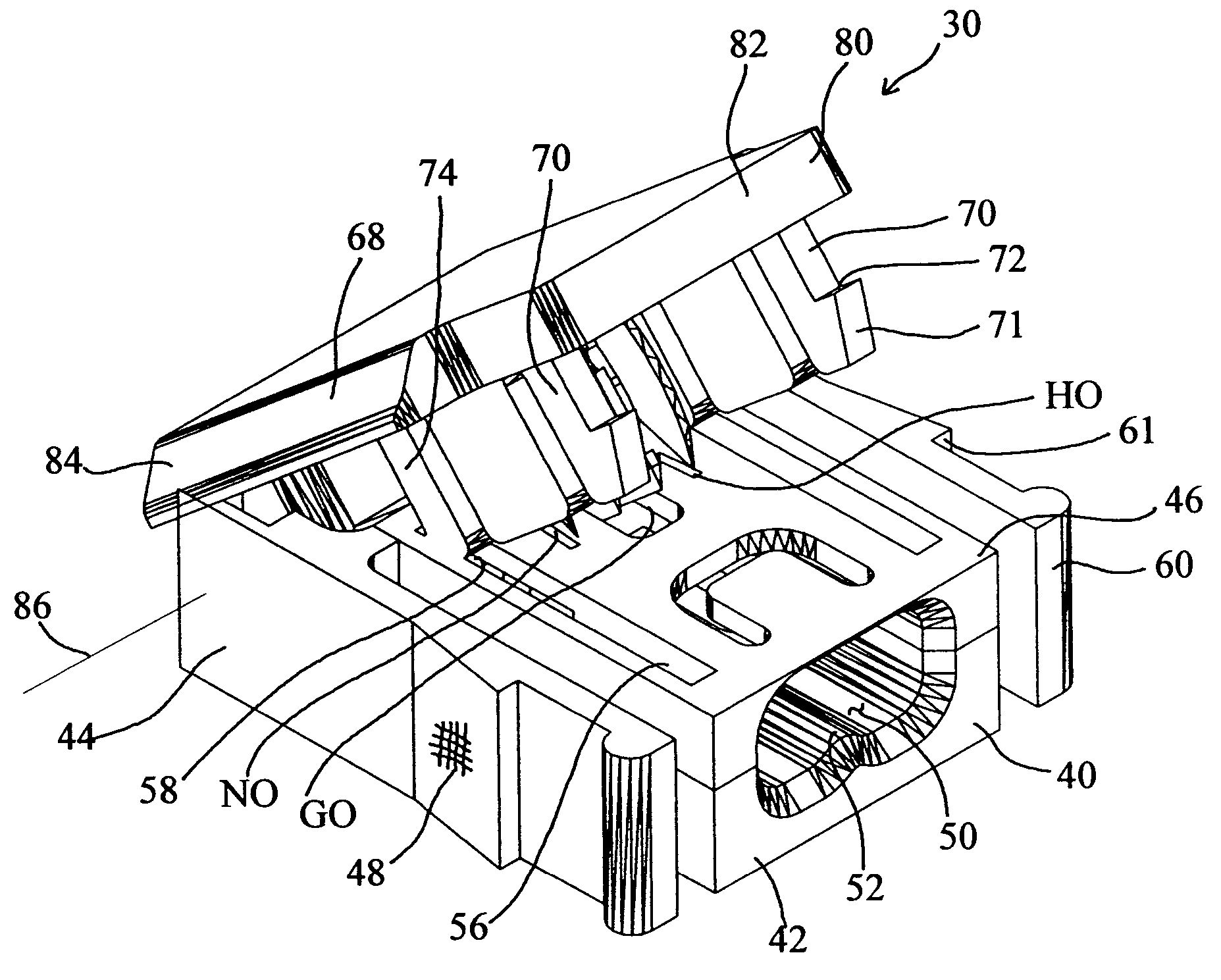
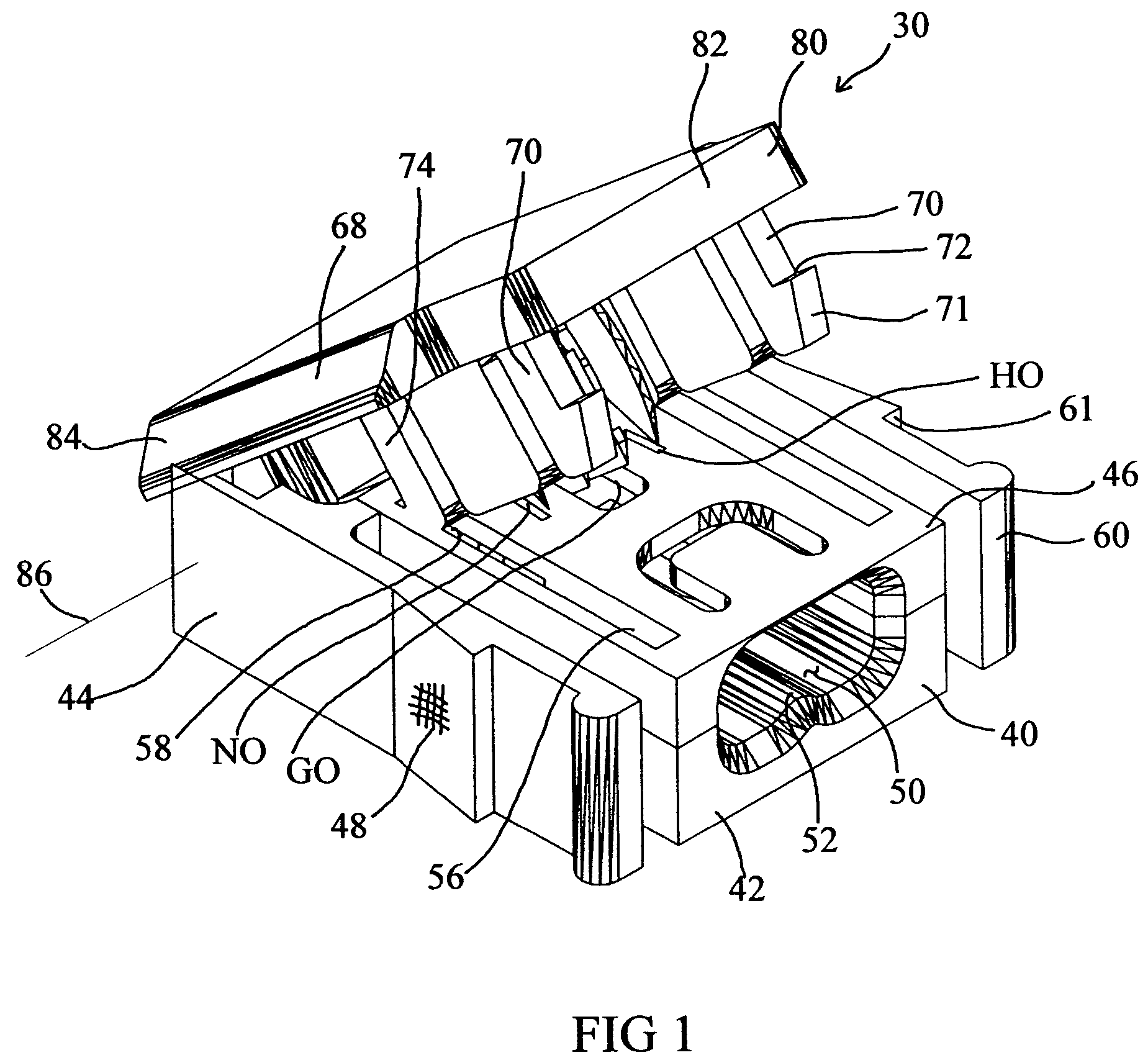
[0060]Referring to the figures, an electrical connector 30 is shown for providing an electrical connection to an unstripped end 12 of an electrical cable 10 which has an outer sheath 14, an insulated hot wire H, an insulted neutral wire N and an insulated ground wire G.

[0061]As best shown in FIGS. 5 and 6, the hot wire H has insulation 16 therearound, neutral wire N has insulation 18 therearound and ground wire G has a paper insulation I therearound. All of these wires are encased in an outer sheath 14 as shown.

[0062]A body 40 is provided from an electrically insulating material. The body 40 has a first end 42 and a second end 44. The body 40 has a cavity 50 in the first body end 42 sized to receive an unstripped end 12 of said insulated electrical cable 10.

[0063]The present invention also includes a lid 80 having a first lid end 82 and a second lid end 84. The second lid end 84 is pivotally connected to the second body end 44 and the lid 80 is adapted to rotate about an axis of rot...


PUM


Abstract

An electrical connector provides an electrical connection to an unstripped end of an insulated electrical cable of the type having an outer sheath within which an insulated hot wire, an insulated neutral wire, and a ground wire are enclosed. The connector has a body formed of an electrically insulating material and a cavity in a first body end sized to receive an unstripped end of the cable. A lid is pivotally connected to the body which is adapted to rotate around an axis of rotation between and open position and a closed position. A hot blade conductor, a neutral blade conductor, and at least one ground blade conductor are positioned in the lid. The blade conductors each have at least one downwardly depending blade and an outlet portion. The blades conductors are spaced apart. When the lid is in open position, the blades do not extend within said cavity. When the lid in a closed, the blades do extend within the cavity and make an electrical connection with the hot, neutral and ground wires of the cable.

Description

BACKGROUND OF THE INVENTION[0001]1. Field of the Invention[0002]The present invention relates to an electrical connector for insulated cable. More particularly, it relates to a connector which can be utilized without tools to quickly and effectively make an electrical connection to a hot conductor wire, a neutral conductor wire and a ground wire which are encased in an outer sheath of a transversely cut unstripped end of insulated electrical cable.[0003]2. Prior Art[0004]It has long been known to provide a body member having a pivotally mounted lid having blade members therein to make an electrical connection to an electrical cord by piercing the insulation with the blade members. An example of such a device is shown and described in Greenbaum, U.S. Pat. No. 2,717,365. The Greenbaum device is effective for quickly attaching an outlet receptacle and a product manufactured in accordance with the teachings of such patent is still being sold as catalog number BP2603B and part number 260...

Claims


Application Information

Patent Timeline
Patent Type & Authority Patents(United States)
IPC IPC(8): H01R4/24H01R13/506
CPCH01R4/2412H01R4/2433H01R13/506
Inventor LIBBY, ROBERT A.DECKER, DEVIN B.
Owner ASLAN INDS
Why Eureka
Try Eureka