Water-resistant casing structure for electronic control device

a casing structure and electronic control technology, applied in the direction of electrical apparatus casings/cabinets/drawers, coupling contact members, securing/insulating couplings, etc., can solve the problems of reducing the service life of the electronic control device. b>101/b>, to achieve the effect of minimizing stresses and reliable operation

Active Publication Date: 2006-12-05
DENSO CORP
View PDF13 Cites 58 Cited by
  • Summary
  • Abstract
  • Description
  • Claims
  • Application Information

AI Technical Summary

Benefits of technology

[0008]It is an object of the present invention to provide a water-resistant casing structure for use with an electronic control device, which is capable of minimizing stresses developed in a water-resistant seal and hence keeping the water-resistant seal effective long enough to allow the electronic control device to operate reliably for a long period of time.
[0010]When the casing at the sealed region tends to be deformed toward the connector due to the pressure difference between the spaces inside and outside of the casing, the tooth whose tip end is held against the casing or the connector prevents the casing from being deformed toward the connector. As a result, stresses imposed on the water-resistant seal are minimized, making the water-resistant seal highly reliable for a long period of time.
[0012]In the above electronic control device, the casing may have the tooth disposed on a wall thereof and having the tip end held against the connector, the wall being resiliently curved toward the connector before the casing is assembled, and after the casing is assembled with the tip end held against the connector, the wall may be normally biased toward the connector under a resilient force imposed by the wall which has been resiliently curved toward the connector before the casing is assembled. When the pressure in the casing becomes higher than the pressure around the casing, the casing is less liable to be deformed outwardly, preventing the water-resistant seal from being peeled off.
[0013]In the above electronic control device, the casing may have the tooth disposed on a wall thereof and extending continuously along the region of the at least one of the parallel sides which is sealed by the water-resistant seal. The tooth thus constructed serves as a rib for stiffening the casing to minimize stresses imposed on the water-resistant seal.
[0014]In the above electronic control device, the casing may include a member providing at least one of the parallel sides, the member being made of synthetic resin with glass fibers mixed therewith. The tooth as a stop is highly effective because the member of the casing tends to suffer warpage due to the orientation of the glass fibers.

Problems solved by technology

The water-resistant seal 104 undergoes greater stresses and may possibly lose its water-resistant capability.
If the sealing function of the water-resistant seal 104 fails, then the electronic control device enclosed in the casing 101 may be damaged by water introduced into the casing 101.

Method used


Image

  • Water-resistant casing structure for electronic control device
  • Water-resistant casing structure for electronic control device
  • Water-resistant casing structure for electronic control device

Examples


1st embodiment

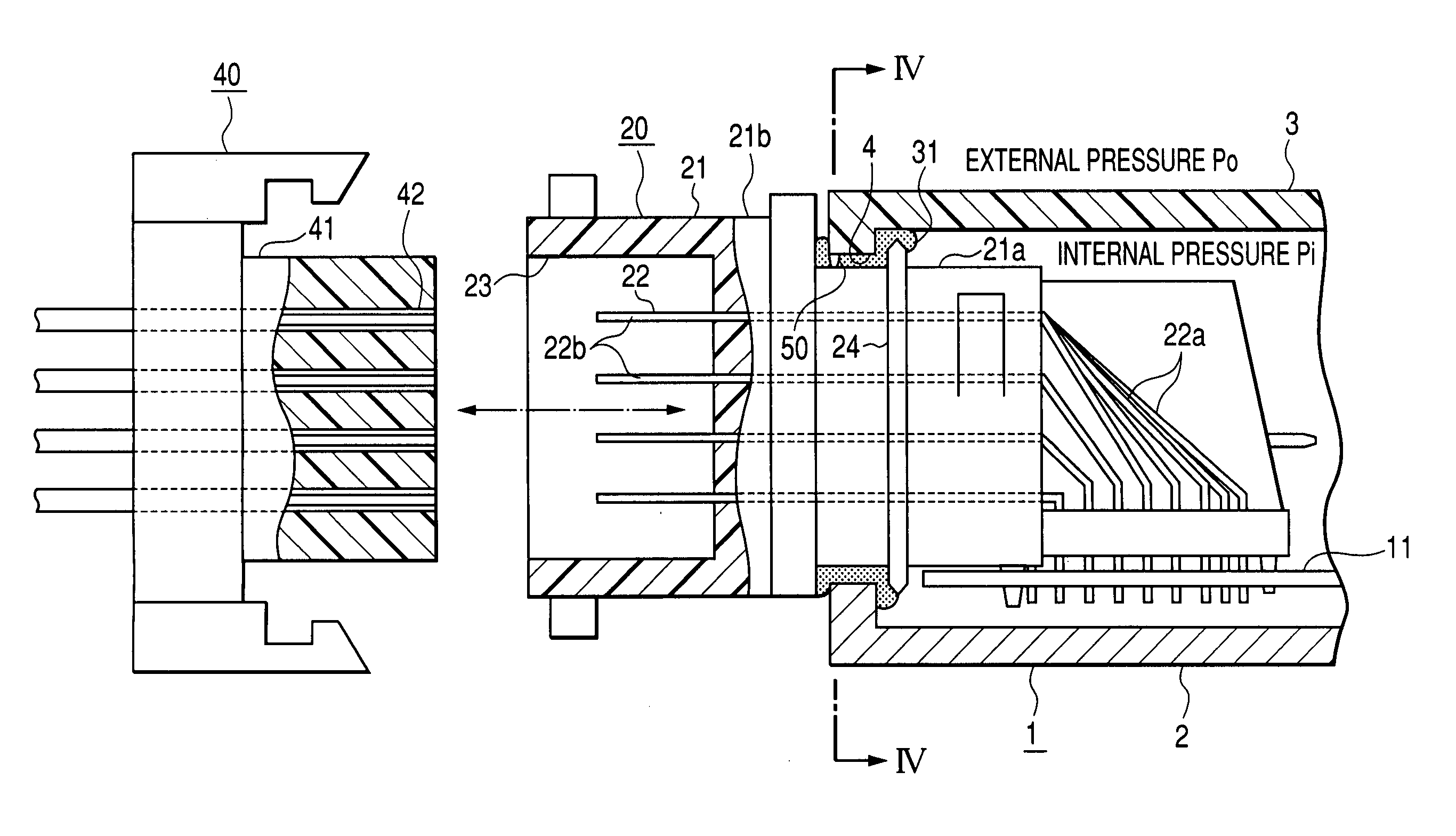
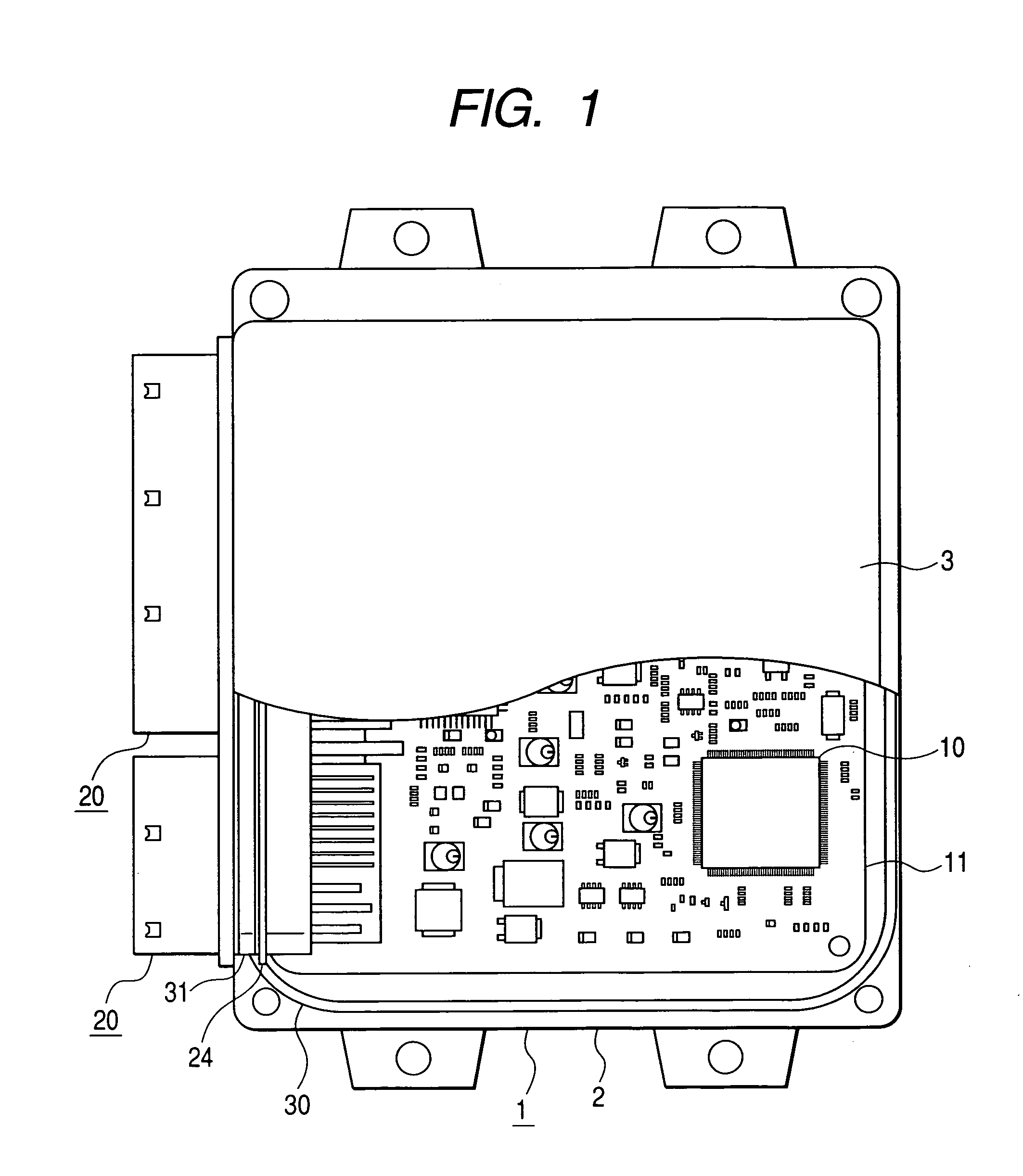
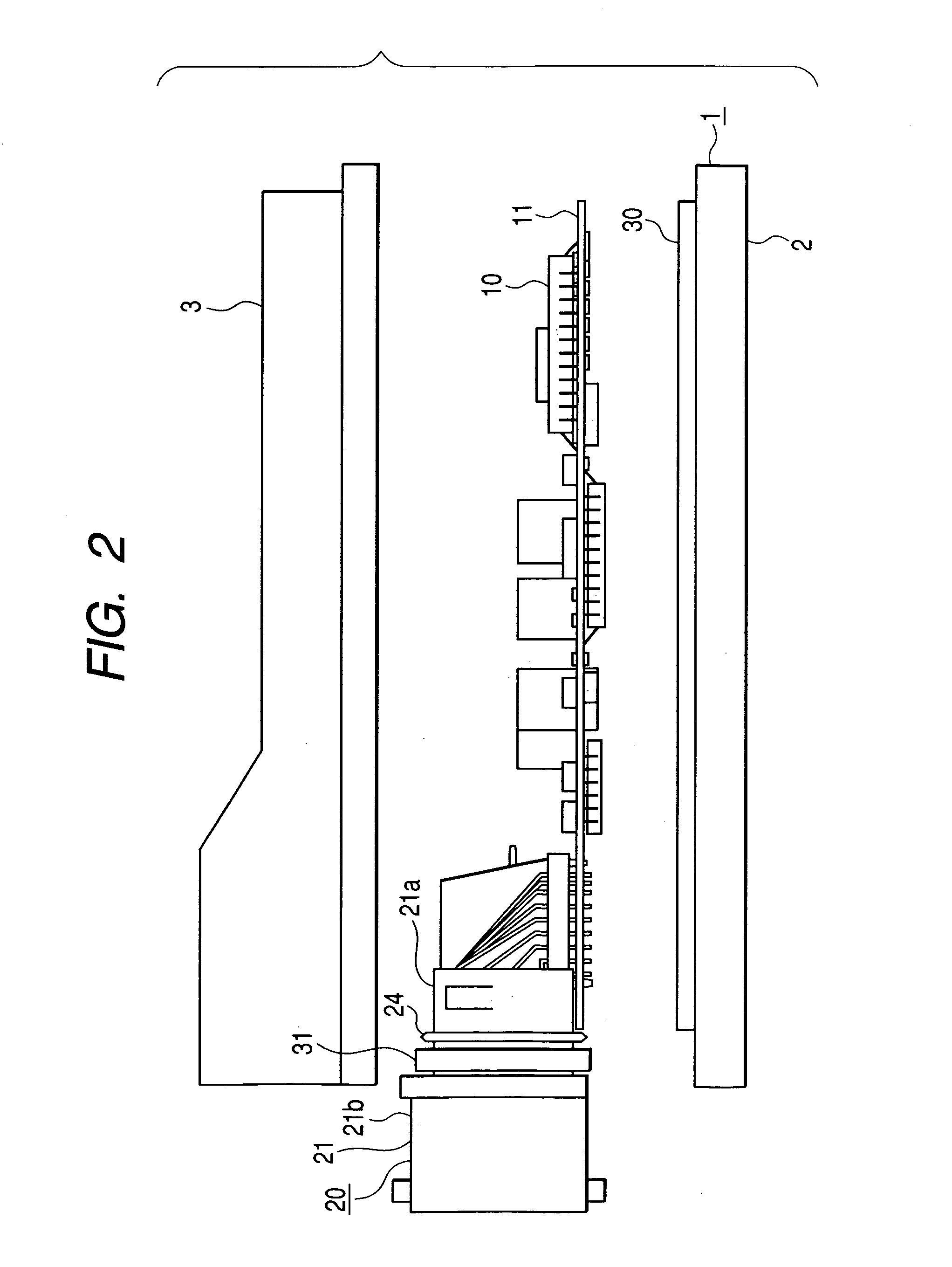
[0043]As shown in FIGS. 1 and 2, a water-resistant casing structure according to a first embodiment of the present invention has a casing 1 housing the electronic control device therein. The casing 1 comprises a lower case 2 serving as a base plate and an upper case 3 serving as a cover. The lower case 2 is in the form of an aluminum die-casting, and the upper case 3 is molded of synthetic resin. The lower case 2 comprises a flat square plate. The upper case 3 comprises a downwardly open square box having a lower opening, and is mounted on the lower case 2 which closes the lower opening of the upper case 3. The lower case 2 and the upper case 3 are fastened to each other by screws, for example, with an annular water-resistant seal 30 interposed therebetween. The annular water-resistant seal 30 hermetically seals the space defined between the lower case 2 and the upper case 3. The box-shaped casing 1 is substantially square in shape as viewed in plan, and has a height much smaller th...

2nd embodiment

[0060]A water-resistant casing structure according to a second embodiment of the present invention will be described below with reference to FIGS. 6, 7, and 8. Only parts of the water-resistant casing structure according to the second embodiment which are different from the water-resistant casing structure according to the first embodiment will be described in detail below.

[0061]According to the second embodiment, as shown in FIGS. 6, 7, and 8, a tooth 60 as a stop is disposed on the casing 1, i.e., the upper case 3 thereof, at a position closely confronting the connector 20 near the region sealed by the water-resistant seat 31.

[0062]Specifically, the inner block member 21a of the connector 21 extends through the joint hole 4 into the casing 1, and has an upper surface closely confronting the upper case 3 of the casing 1. The tooth 60 is disposed at a central position in the horizontal direction in FIG. 7. The tooth 60 is integrally formed with the upper case 3 in a region which is ...

3rd embodiment

[0064]A water-resistant casing structure according to a third embodiment of the present invention will be described below with reference to FIGS. 9, 10, and 11. Only parts of the water-resistant casing structure according to the third embodiment which are different from the water-resistant casing structure according to the second embodiment will be described in detail below.

[0065]According to the third embodiment, as shown in FIGS. 9, 10, and 11, a tooth 70 as a stop is disposed on the connector 20, i.e., the inner block member 21a thereof, at a position closely confronting the casing 1 near the region sealed by the water-resistant seat 31.

[0066]Specifically, the tooth 70 is integrally formed with an upper surface of the inner block member 21a in a region which is positioned slightly inwardly of the water-resistant seal 31, i.e., in a region which is not contacted by the water-resistant seal 31. The tooth 70 is disposed at a central position in the horizontal direction in FIG. 10. T...


PUM


Abstract

A circuit board supporting electronic components mounted thereon is housed in a casing. The casing has a joint hole defined therein, and a connector is inserted in the joint hole with a water-resistant seal placed in a gap between the connector and edges of the casing which define the joint hole. The casing is of a trapezoidal shape and has a pair of parallel sides spaced from each other by a distance, the parallel sides having respective lengths greater than the distance between the parallel sides. The casing has a tooth as a stop which has a tip end held against the connector at a position in which the casing and the connector closely confront each other in or near a region of at least one of the parallel sides which is sealed by the water-resistant seal.

Description

CROSS-REFERENCE TO RELATED APPLICATIONS[0001]This application is based upon and claims the benefits of priority from the prior Japanese Patent Application No. 2004-250910, filed on Aug. 30, 2004, and the prior Japanese Patent Application No. 2005-185515, filed on Jun. 24, 2005, the entire contents of which are incorporated herein by reference.BACKGROUND OF THE INVENTION[0002]1. Field of the Invention[0003]The present invention relates to a water-resistant casing structure for use with an electronic control device.[0004]2. Description of the Related Art[0005]One known water-resistant casing structure for use with an electronic control device for vehicle-mounted engine control, for example, employs a rubber gasket as disclosed in Japanese laid-open patent publication No. H10-22658.[0006]The disclosed water-resistant casing structure will be described below with reference to FIGS. 17, 18A, and 18B of the accompanying drawings. FIG. 17 is a fragmentary cross-sectional view of a water-re...

Claims


Application Information

Patent Timeline
Patent Type & Authority Patents(United States)
IPC IPC(8): H01R13/40
CPCH05K5/0069H05K5/062
Inventor IIDA, TAKU
Owner DENSO CORP
Why Eureka
Try Eureka