Memory card connector

a memory card and connector technology, applied in the direction of coupling device connection, electrical apparatus casing/cabinet/drawer, instruments, etc., can solve the problems of large inconvenience of inserted memory cards may drop out of the card cavity, etc., to facilitate insertion/extraction of memory cards and save time.

Inactive Publication Date: 2006-12-05
CHENG UEI PRECISION IND CO LTD
View PDF6 Cites 10 Cited by
  • Summary
  • Abstract
  • Description
  • Claims
  • Application Information

AI Technical Summary

Benefits of technology

[0007]Therefore, it is an object of the present invention to solve the above problems and provide a memory card connector, which facilitates insertion / extraction of a memory card with saving time, and holds the inserted memory card reliably and exactly therein.
[0009]On the basis of mentioned above, when the memory card connector is installed in the back shell of a cellular phone, the slide cover is conveniently pulled out of the cellular phone so that the memory card is conveniently inserted into the card cavity of the slide cover and slides along with the slide cover into the cellular phone until the locking recess of the slide cover engages with the locking tab of the base member disposed in the cellular phone. Thus, the memory card can be reliably and exactly positioned in the memory card connector to make proper electrical connection with the contacts on the base member. In addition, the slide cover mounted with the memory card can be conveniently pulled out of the cellular phone for extracting of the memory card from the memory card connector. Therefore, comparing with the prior art, the memory card connector 100 according to the present invention also can facilitate insertion / extraction of the memory card with saving much time.

Problems solved by technology

However, since such conventional memory card connector as above has no specialized locking mechanism for reliably and exactly positioning the inserted memory card in the card cavity, there has been a risk that the inserted memory card may drop out from the card cavity when an impact force is applied from the exterior.
In addition, the aforementioned memory card connector assembled in the back shell of the cellular phone causes great inconvenience to the insertion / extraction of the memory card with time wasting.

Method used


Image

  • Memory card connector
  • Memory card connector
  • Memory card connector

Examples


Embodiment Construction

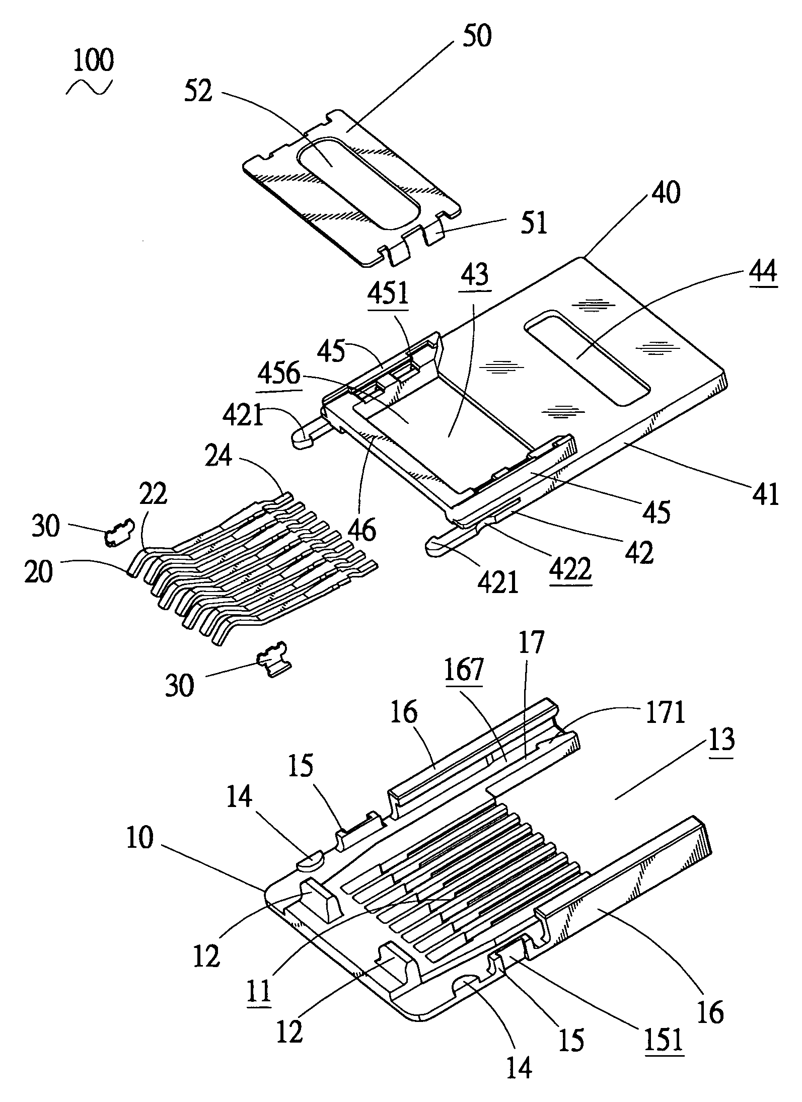
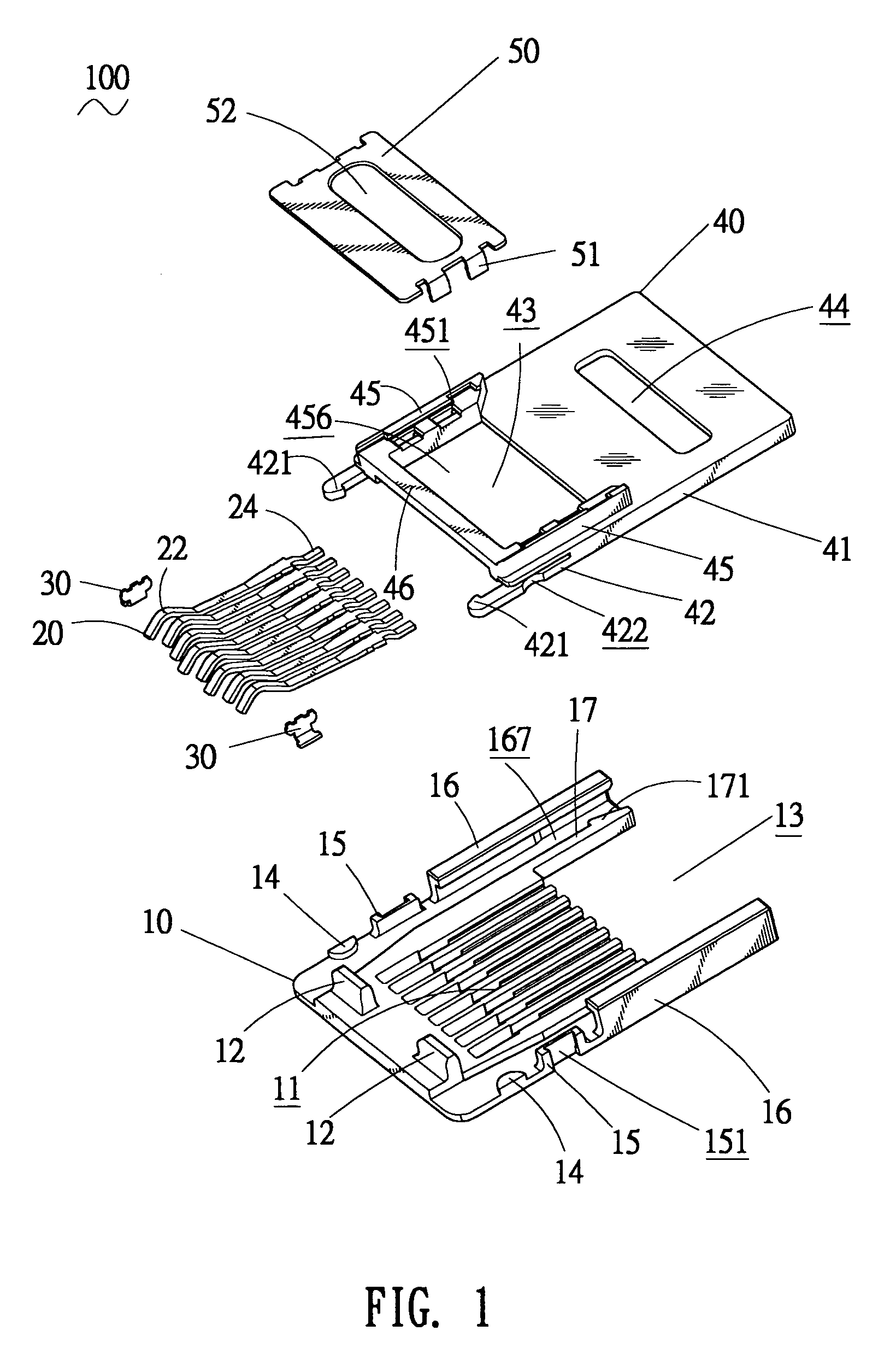
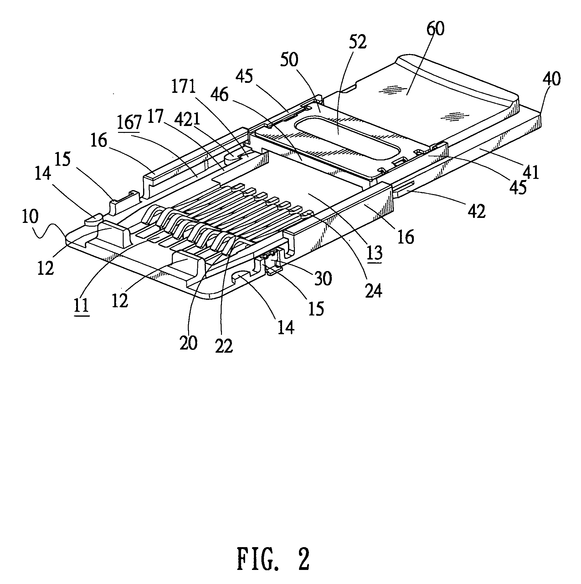
[0014]With reference to FIGS. 1 and 2, the memory card connector 100, in accordance with the present invention, comprises a dielectric base member 10 that holds a plurality of contacts 20 thereon. Each contact 20 has a contact section 22 for making electrical connection with a memory card 60 and a solder section 24 connecting with the contact section 22 for making electrical and mechanical connection with an external circuit board (not shown) by soldering. A slide cover 40 slidably engages with the base member 10 and has an upper lid 50 disposed thereon for securing the memory card 60 between the slide cover 40 and the upper lid 50. In the present embodiment, the memory card 60 is a Transflash memory card.

[0015]The base member 10 is constructed with a pair of locking arms 17 disposed at a rear portion thereof and a rear opening 13 formed between the locking arms 17. Each locking arm 17 further has a positioning hook 171 extending outwardly from the free end thereof for attaching the...


PUM


Abstract

A memory card connector includes a base member, a plurality of contacts held on the base member and a slide cover slidably engaging with the base member. The base member has a rear opening, a pair of longitudinal guiding slots respectively defined at two opposite sides thereof, and a pair of locking tab disposed thereon. The sliding cover has a card cavity for receiving a memory card, an engaging slot defined at a rear portion thereof corresponding to the rear opening, and a pair of slide arms for sliding in the corresponding guiding slots. Each slide arm extends forwards to form a resilient arm with a locking recess defined therein for engaging with the corresponding locking tab. Therefore, as used in a cellular phone, the memory card connector can facilitate insertion / extraction of the memory card and hold the memory card reliably and exactly therein.

Description

BACKGROUND OF THE INVENTION[0001]1. Field of the Invention[0002]The present invention relates generally to a card connector, and particularly, to a memory card connector which is so structured that it can facilitate insertion / extraction of a memory card thereinto / therefrom and hold the inserted memory card reliably and exactly therein.[0003]2. The Related Art[0004]Recently, because of the multi-function combination and greater compactness of the cellular phone or the like, there is an extensive need of a TransFlash memory card having larger storage and smaller size, and correspondingly, various types of memory card connectors have been designed for conforming to the TransFlash memory card structure.[0005]These existing memory card connectors commonly include a dielectric housing which holds a plurality of contacts therein, and a cover mating with the housing to form a card cavity for inserting of a memory card. As one of these conventional memory card connectors is assembled in the ...

Claims


Application Information

Patent Timeline
Patent Type & Authority Patents(United States)
IPC IPC(8): H01R24/00
CPCG06K13/08G06K13/085H01R13/2442
Inventor YANG, MEI CHUAN
Owner CHENG UEI PRECISION IND CO LTD
Why Eureka
Try Eureka