Foot unit for abrasive cutting-off machine

a cutting-off machine and foot unit technology, applied in the field of work devices, can solve the problems of increased cost of acquisition, unsuitability of manual operation, and inability to meet the needs of stone-like material working apparatus, and achieve the effect of increasing wear

Inactive Publication Date: 2006-12-05
DOLMAR
View PDF32 Cites 17 Cited by
  • Summary
  • Abstract
  • Description
  • Claims
  • Application Information

AI Technical Summary

Benefits of technology

[0006]The present invention addresses the above-mentioned issues by making a work device available that can be comfortably guided in a work position and is stable in a turned-off position without components relative to safety being exposed to increased wear. In particular, the work device (such as an abrasive cutting-off machine) has a foot unit having at least one rolling means and at least one support. The foot unit makes it possible to guide the abrasive cutting-off machine on the at least one rolling means in the work position and to set it on the support in the turned-off position. The work device is not resting on components that have safety concerns, and as a result of this they are protected from wear.

Problems solved by technology

In particular, in order to make long cut lines or expansion joints in floor coverings, the manual operation requires a great amount of force and is therefore unsuitable.
Guide carriages are large devices whose acquisition entails additional expense.
However, an abrasive cutting-off machine is not particularly stable in this design and moves on the floor space via the non-fixed roller on account of its idling vibrations.
The bracket handle is exposed to increased wear due to friction, caused by vibrations, with the floor space.
However, bracket handles are components of the abrasive cutting-off machine that are subject to particularly strict safety conditions.

Method used


Image

  • Foot unit for abrasive cutting-off machine
  • Foot unit for abrasive cutting-off machine
  • Foot unit for abrasive cutting-off machine

Examples


Embodiment Construction

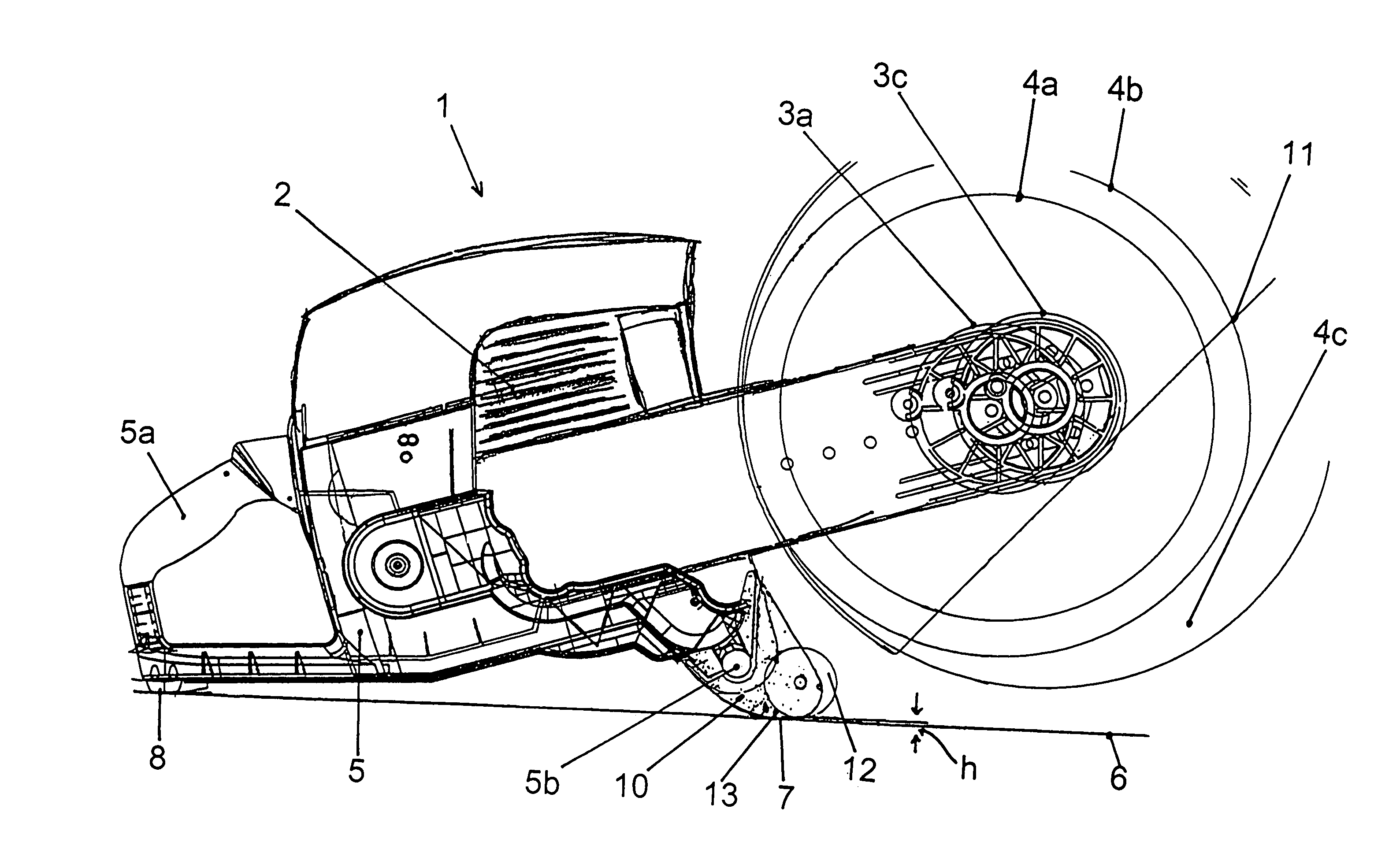
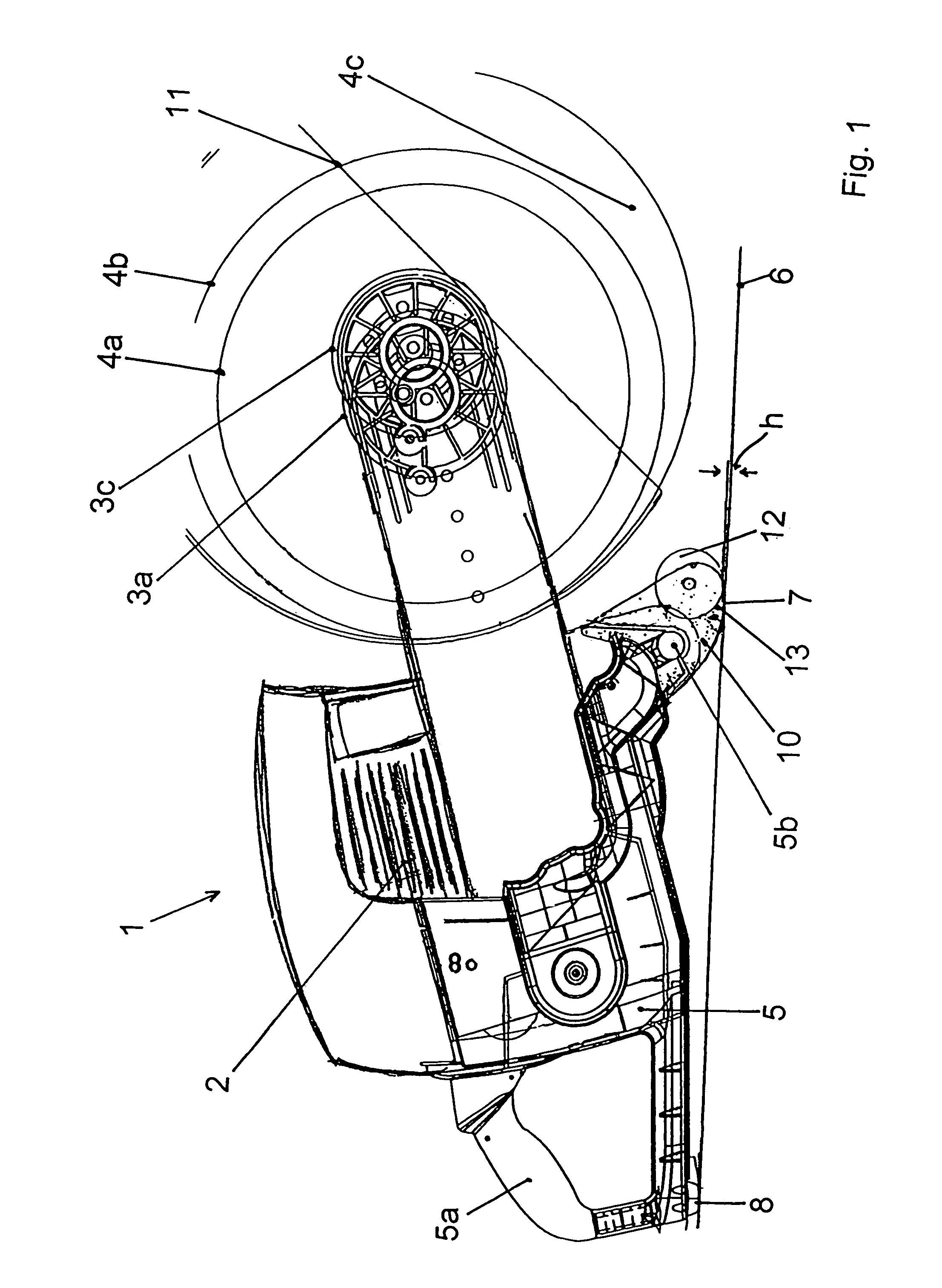
[0010]The invention entails a work device such as the type mentioned above, in particular an abrasive cutting-off machine, with a foot unit on which the at least one rolling means and the at least one support are arranged. As noted above, the foot unit makes it possible to guide the abrasive cutting-off machine on the at least one rolling means in the work position and to set it on the support in the turned-off position. In particular, the abrasive cutting-off machine is not set on components relevant to safety and as a result of this they are protected from wear.

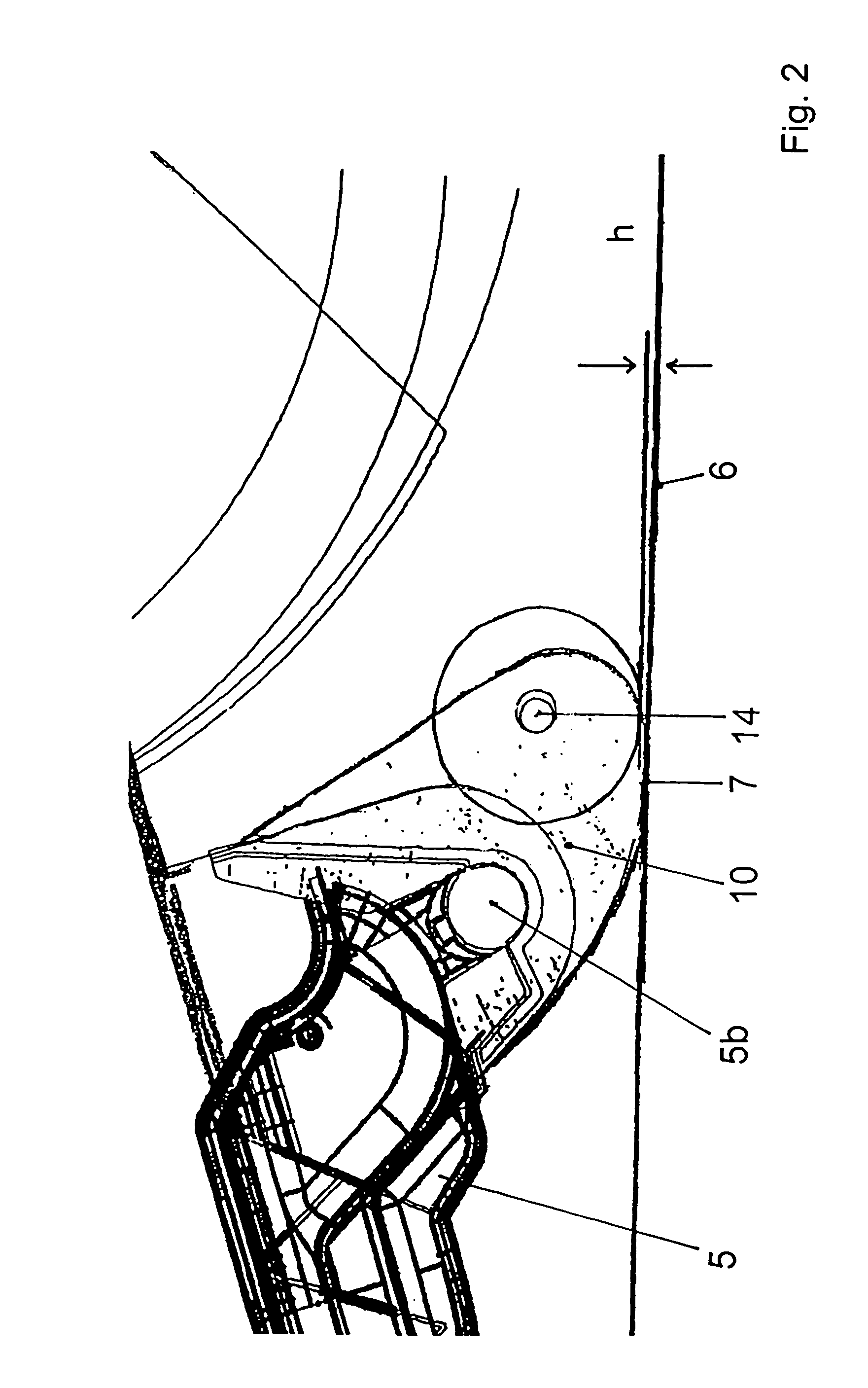
[0011]The at least one support cooperates with the at least one rolling means since the abrasive cutting-off machine can be tilted between the turned-off position and the work position and in the first position the support and in the second position the rolling means makes contact with the floor space. In order that the functional interrelation can be taken into account better, the foot unit comprises the at least one suppo...


PUM

PropertyMeasurementUnit
radiusaaaaaaaaaa
heightaaaaaaaaaa
widthaaaaaaaaaa

Abstract

The invention described here entails a work device (such as an abrasive cutting-off machine) that can be comfortably guided in a work position and is stable in a turned-off position without components relative to safety being exposed to increased wear. In particular, the work device has a foot unit having at least one rolling means and at least one support. The foot unit makes it possible to guide the abrasive cutting-off machine on the at least one rolling means in the work position and to set it on the support in the turned-off position.

Description

FIELD OF THE INVENTION[0001]This application claims priority from German utility model application DE 20 2004 007 699.3, filed May 13, 2004.[0002]The invention relates to a work device, in particular an abrasive cutting-off machine, with at least one support on which the abrasive cutting-off machine can be set in a turned-off position on a floor space and that can be shifted from the turned-off position into a work position by being tilted about the at least one support, and with at least one rolling means arranged between the support and a cutting disk, which means contacts the floor space in the work position.BACKGROUND OF THE INVENTION[0003]Work devices in the form of abrasive cutting-off machines are sufficiently known. Abrasive cutting-off machines can be used in various ways by a user. In manual operation the abrasive cutting-off machine can be grasped on two handles by the user and must be carried and guided on the two handles by the user in order to make short cut lines. In ...

Claims


Application Information

Patent Timeline
Patent Type & Authority Patents(United States)
IPC IPC(8): B24B23/00B28D1/04B24B27/08
CPCB24B27/08B28D1/045
Inventor JAENSCH, WOLFGANG
Owner DOLMAR
Why Eureka
Try Eureka