
Electric field proximity keyboards and detection systems

a detection system and proximity keyboard technology, applied in the field of electric field proximity detection systems, can solve the problems of complicated detection system, cost affecting the adoption rate of these types of keyboards, and the use of touch sensitive and close proximity keyboards, so as to reduce complexity, reduce costs, and improve the resolution

Active Publication Date: 2006-12-05
SOLECTRON
View PDF13 Cites 181 Cited by
  • Summary
  • Abstract
  • Description
  • Claims
  • Application Information

AI Technical Summary

Benefits of technology

[0005]In other features, the electric field proximity detection systems use row and column address schemes to multiplex the electrodes. The row and columns can be nested to permit higher resolution. The address schemes generally reduce complexity, and costs by reducing the addresses. The electric field proximity circuits, arrangements of electrodes, and address schemes are not limited to the keyboards and extend to applications related to object detection such as remote sensing, motion detection and remote control. By increasing the resolution using the row and column schemes, the waveform characteristics change accordingly. The controller can store the different loaded state waveforms characteristics for various objects for analysis and identification of the object types, and distance and duration of the object.

Problems solved by technology

In the past, touch sensitive and close proximity keyboards have used complicated detection systems.
Due to the complexity of these detection designs, the costs impact the adoption rates of these types of keyboards.

Method used


Image

  • Electric field proximity keyboards and detection systems
  • Electric field proximity keyboards and detection systems
  • Electric field proximity keyboards and detection systems

Examples


Embodiment Construction

[0014]The following description includes the best mode of carrying out the invention. The detailed description is made for the purpose of illustrating the general principles of the invention and should not be taken in a limiting sense. The scope of the invention is determined by reference to the claims.

[0015]We assign each part, even if structurally identical to another part, a unique reference number wherever that part is shown in the drawing figures. A dashed circle indicates a portion of a figure that is enlarged in another figure. The figure showing the enlarged portion is indicated by a reference number tied to the dashed circle.

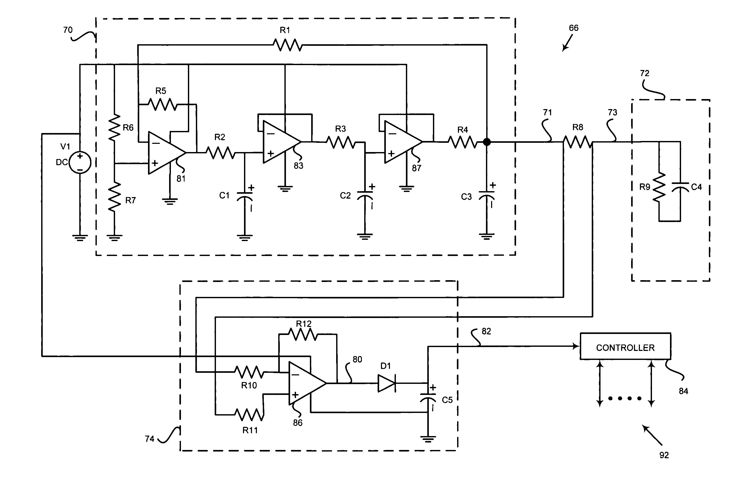
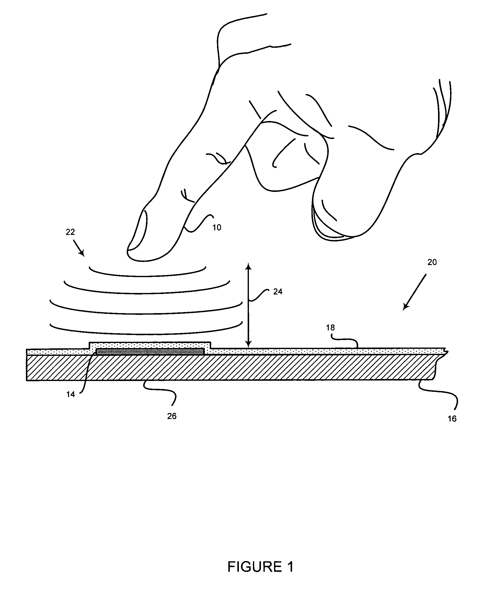
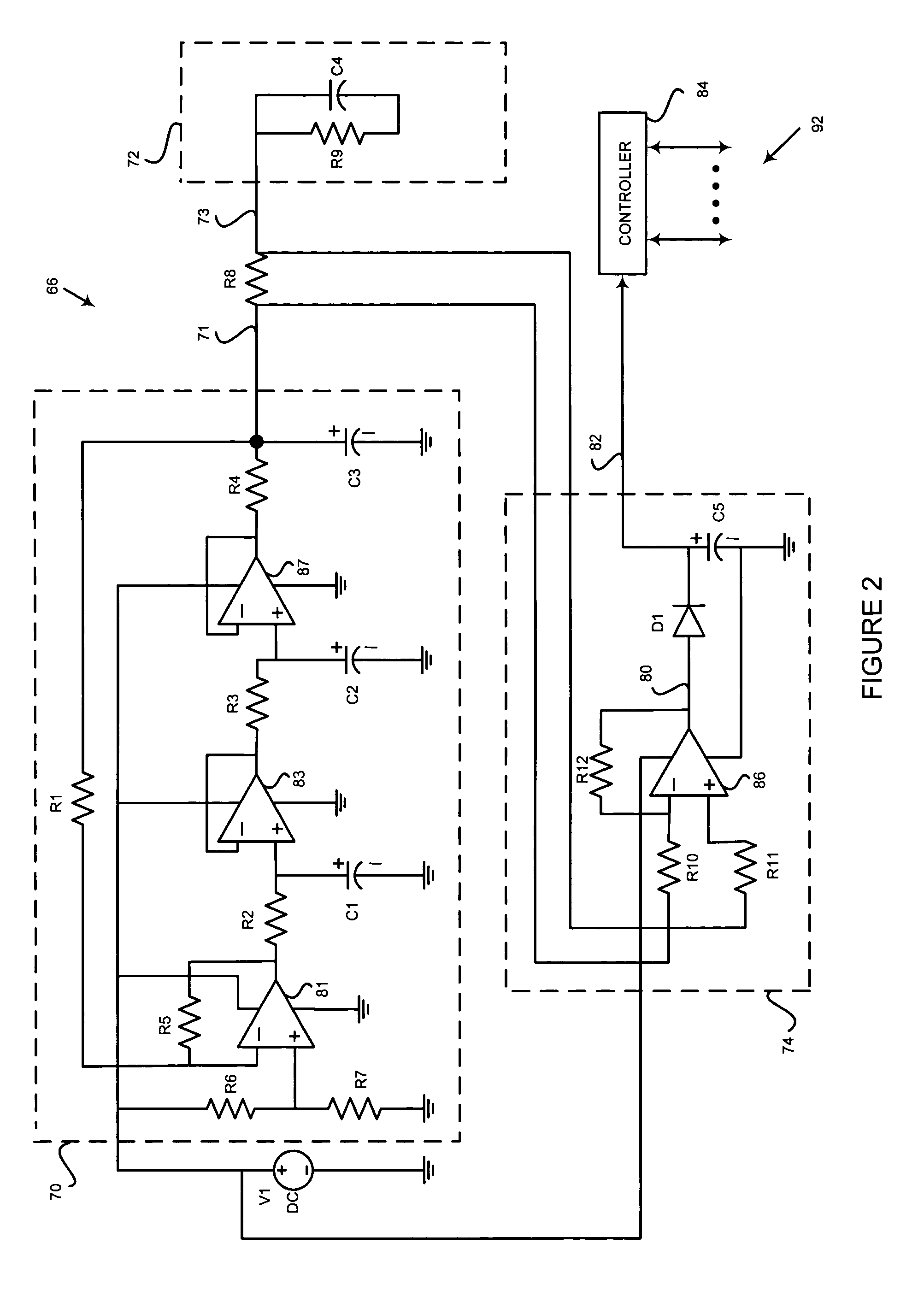
[0016]FIG. 1 illustrates an electric field proximity keyboard 20 that includes a substrate 16 such as a printed circuit board (PCB) and one or more keypads each with an electrode 14. Each electrode can be made, for example, by conductive patterns on the PCB and is connected to an AC signal source described further in connection with FIG. 2. The electrod...


PUM


Abstract

The invention is related to an electric field proximity detection system suitable for use as a touch sensitive keyboard or to be used in close proximity without direct contact. In an embodiment of a circuit useful in the system, an AC signal is coupled to a single electrode functioning as an antenna radiating an electric field through a high impedance circuit. A conductive object in close proximity disturbs the field causing a voltage change across nodes of the high impedance circuit that is compared by a detector circuit that generates a DC output indicating an object is close to the electrode. In another embodiment, the circuit couples to an analog multiplexer to control a plurality of electrodes. In another embodiment, a row and column address scheme couples a plurality of electrodes and increases resolution without substantially increasing complexity. The circuits may be integrated in a semiconductor to reduce size and cost. The electric field proximity detection system extends to applications related to object detection such as remote sensing, motion detection and remote controls.

Description

BACKGROUND[0001]This invention relates to electric field proximity detection systems and particularly to electric field proximity circuits for touch sensitive or close proximity keyboards.[0002]Many keyboards today are activated by depressing a keypad. A touch sensitive keyboard provides a similar I / O device, but is activated by merely touching rather than depressing each keypad. Touch sensitive keyboards are used in a variety of applications such as handheld computing devices (e.g., PDA), musical instruments, elevator switches, appliances, bank ATMs, and computers. Other types of touch sensitive keyboards can be activated by an object such as a finger or stylus touching the keypads displayed on a computer or terminal. A close proximity keyboard does not require contact, but is activated when an object (e.g., stylus or finger) is detected in close proximity to the keypad. Close proximity means the object is at a distance that should be detected for activation. The close proximity ke...

Claims


Application Information

Patent Timeline
Patent Type & Authority Patents(United States)
IPC IPC(8): G09G5/00G06F3/02G06F3/044H01LH03K17/96
CPCG06F3/02G06F3/044H03K17/9622H03K2017/9604
Inventor HOLLINGSWORTH, TOMMY D.
Owner SOLECTRON
Learn More