

Fishing pole holder
- Summary
- Abstract
- Description
- Claims
- Application Information
AI Technical Summary
Benefits of technology
Problems solved by technology
Method used
Image

Examples
Embodiment Construction
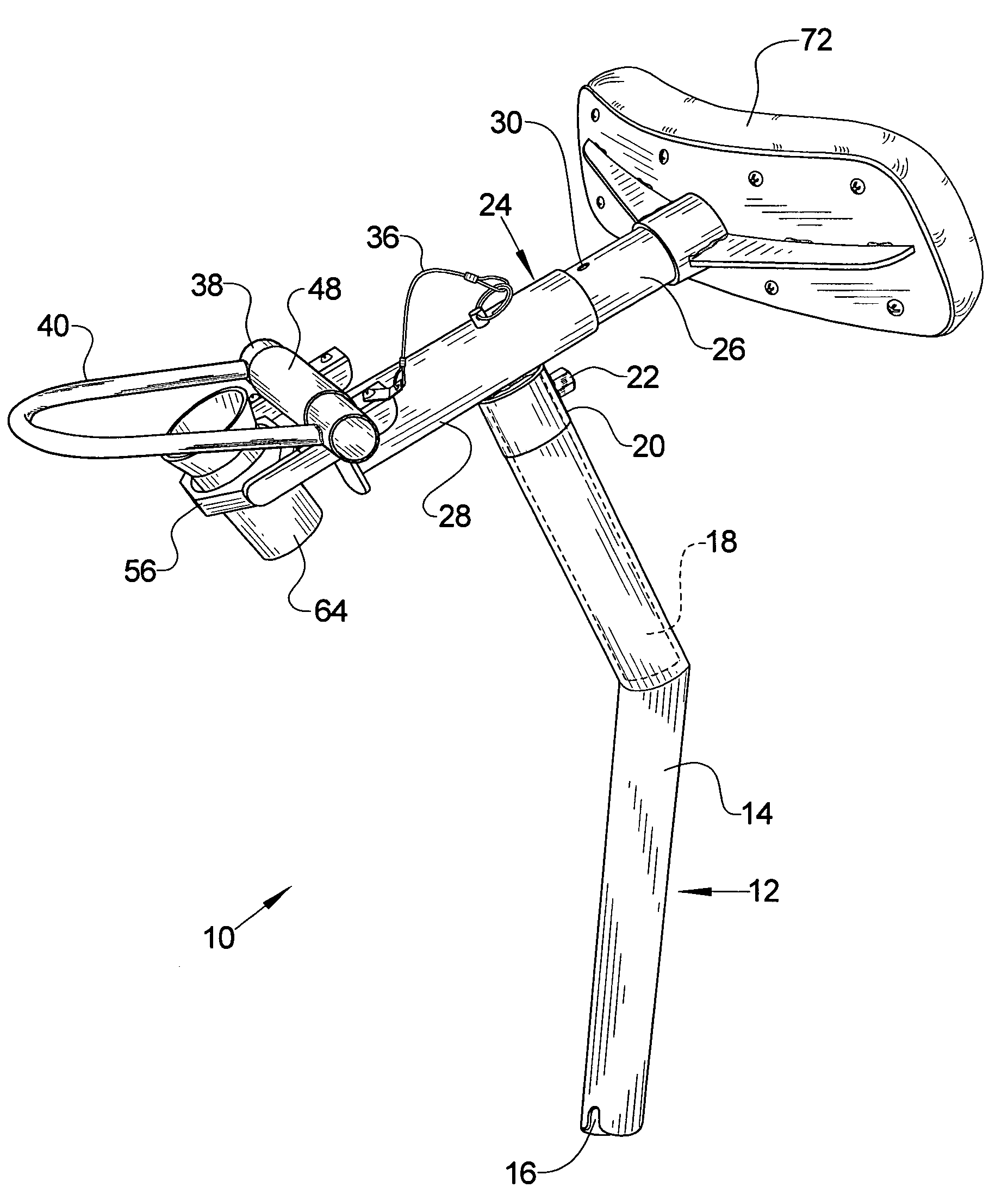
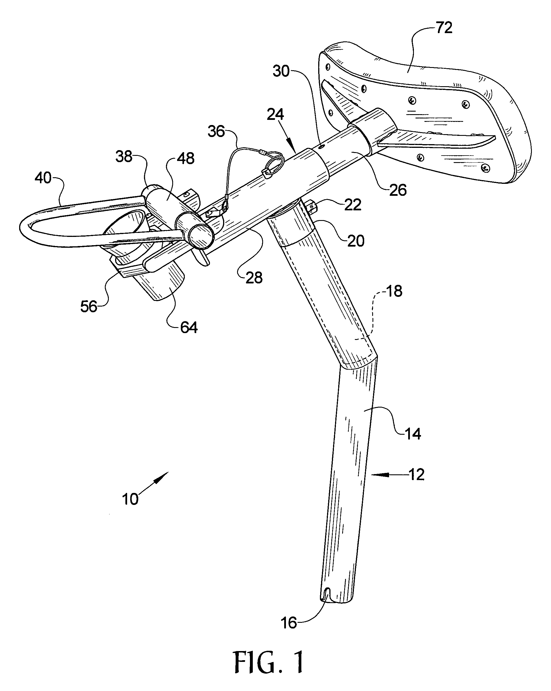
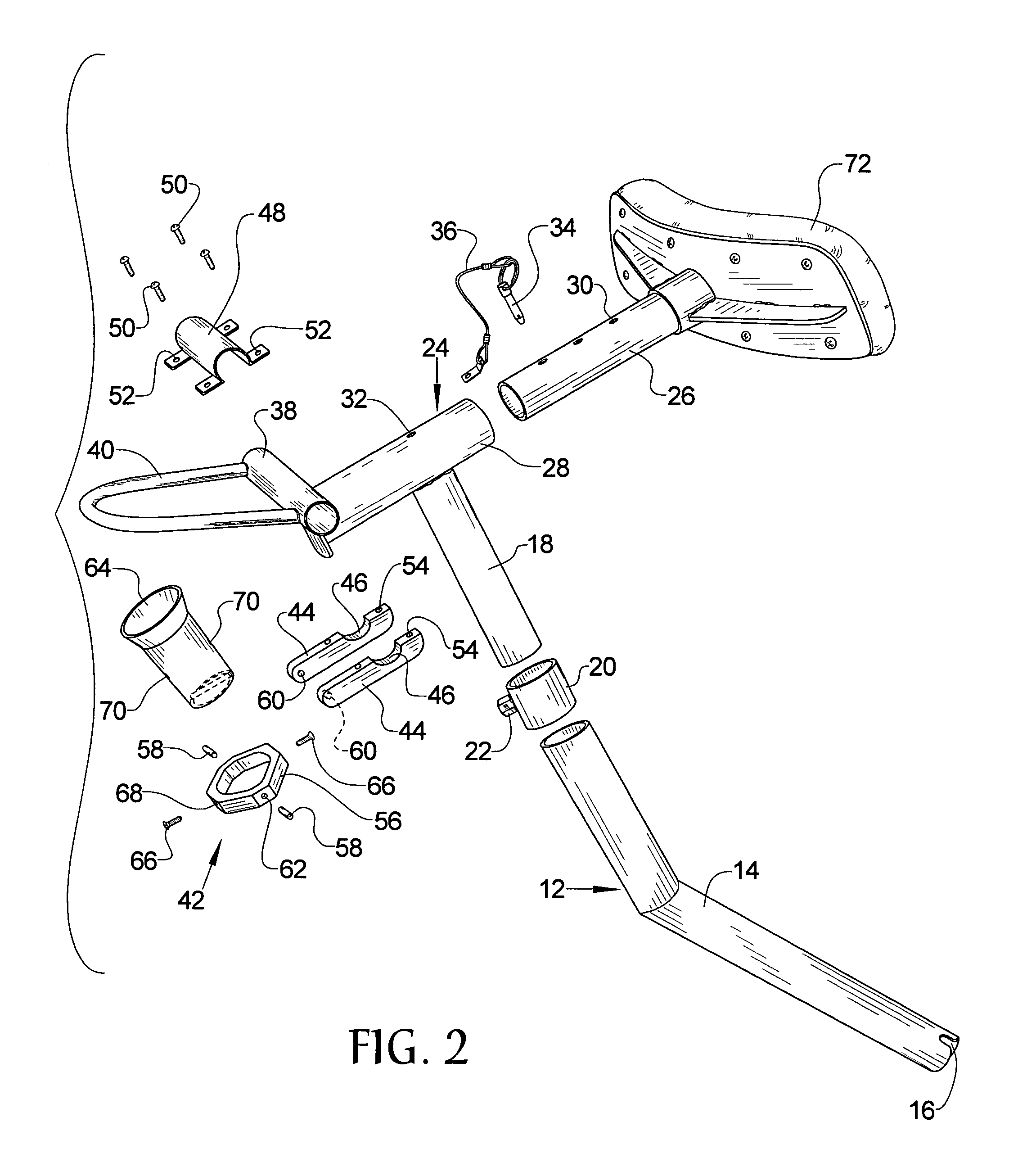
[0012]Referring now to the drawings, it is seen that the fishing pole holder of the present invention, generally denoted by reference numeral 10, is comprised of a stanchion 12 that is telescoping. As seen, the stanchion 12 has a lower section 14 that is a hollow tubular member that has a notch 16 and is bent at an obtuse angle and an upper section 18 that is received within the lower section 14 and is positioned at a desired height within the lower section 14 in order to achieve the telescoping ability of the stanchion 12. A locking collar 20 slides along the length of the upper section 18 and has a set screw 22 that presses against the upper section 18 in order to prevent the locking collar 20 from sliding therealong. Therefore, in order to set the height of the stanchion 12, the locking collar 20 is positioned along the upper section 18 and when at the desired position, the set screw 22 is rotated in order to press against the upper section 18 and thereby prevent the locking coll...
PUM
 Abstract
Description
Claims
Application Information