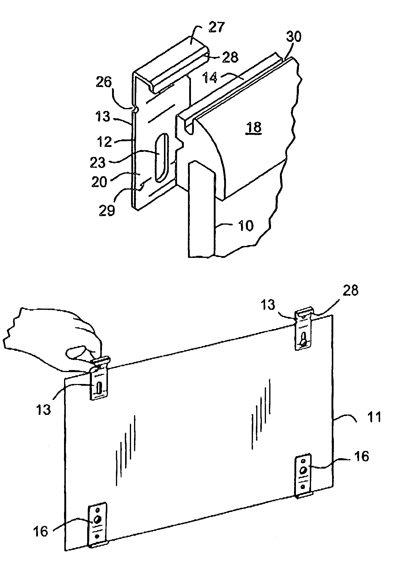
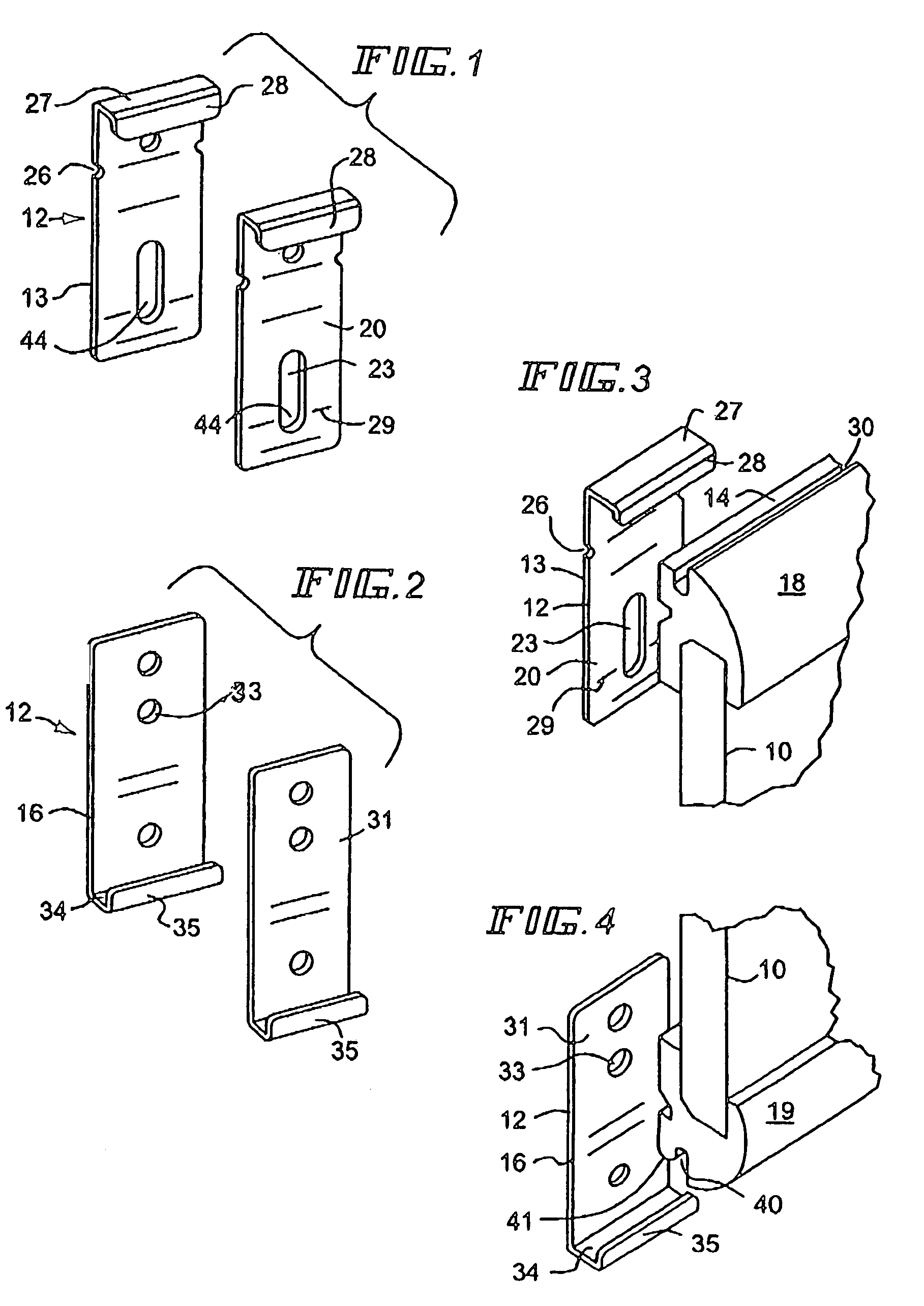
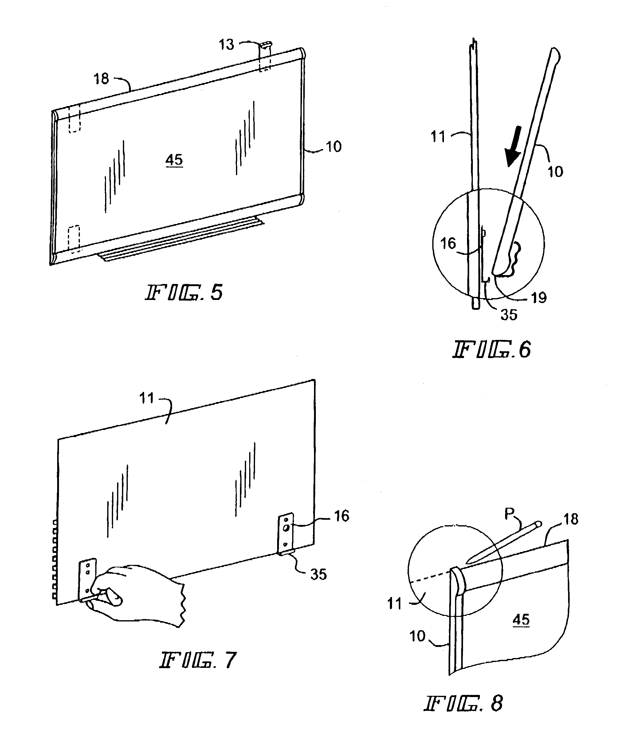
[0032]An display board or frame 10 is shown in FIG. 5 mounted on a wall 11 using the novel brackets 12 embodying the present invention. With reference particularly to FIGS. 1–4, these brackets 12 comprise one or more upper brackets 13 and one or more lower brackets 16, which are adapted to fit cooperating configured areas on the upper and lower edges, 18 and 19 of the frame 10.
[0033]With reference to FIGS. 1 and 3, an upper bracket 13 comprises a generally flat plate 20 having an upstanding flange on its upper end and holes formed in the plate 20. A hole located in the bottom part of the plate 20 comprises an elongated slot 23, and the other hole near the top of the plate may comprises around aperture. Cooperating dimples or indentations 26 extend inwardly from the edges of each plate 20. The flange comprises a header 27 generally perpendicular to the plate 20 and a depending hook 28 extending downwardly from the header 27 and generally parallel to the plate 20. On each side of the plate 20 adjacent the lower end of the slot 23 there are aligned arrow indicia 29. These upper bracket parts described are also shown in FIG. 3, which also depicts a frame 10 having an upper edge 18 which has a channel 30 adapted to receive therein the header 27 and hook 28 of the upper bracket 13 when the frame is mounted on a wall as hereinafter described. Preferably the outside part 14 of the upper edge 18 of the frame has relief or a recess cut into it to accommodate the header 27 and hook 28 of the flange.
[0034]With reference to FIGS. 2 and 4, a lower bracket 16 comprises a generally flat plate 31 having an upstanding flange on its lower end and mounting holes formed in the plate 31. Preferably these holes 33 may be used to for mounting this lower bracket to the wall 11. The flange comprises a base 34 generally perpendicular to the plate 31 and an upstanding hook 35 extending from the base and generally parallel to the plate 31. These lower bracket parts described are also shown in FIG. 4, which depicts a frame 10 having a lower edge 19 which has a channel 40 adapted to receive therein the base 34 and hook 35 of the lower bracket 16 when the frame is mounted on the wall as hereinafter described. Preferably outside part 41 of the lower edge 19 also has a relief cut into it to accommodate its related base 34 and hook 35.
[0035]To mount the easel or frame 10 on a wall 11, the intended location of the board on the wall is ascertained, whereupon one of more of the lower brackets 16 is secured to the wall, preferably using wall anchors and screws, fastening the brackets to the wall by using the lower plate mounting holes 33 in the lower bracket plate 31, as shown in FIG. 7, in a position to receive the lower frame edge 19 of the display board or frame. Making sure that the easel frame 10 is level, and then seating it on the lower bracket flange base 34 and hook 35 which engage the lower frame channel 40, in the direction of the arrow shown in FIG. 6. The easel frame is swung against the wall 11, and the location of upper frame edge 19 is marked on the wall with a pencil P or the like, as depicted in FIG. 8, and a level mark is extended similarly to the intended right side of the upper frame edge.
[0036]With the intended location of the upper brackets 13 ascertained, these brackets are secured to the wall, as shown in FIGS. 9–11, using the bracket dimples 26 to indicate the location for the upper frame edge 18. With reference to FIG. 10, the position of the bottom of slot 23 on the upper bracket plate 20 is marked with a pencil P or the like, using the arrow indicia 29 marked thereon. An anchor 42 may be installed in the wall 11 and a screw 43 may be threaded therein in the bottom 44 of the slot 23, but this screw should not be overly tightened, to permit the bracket to move in the slot.
[0037]As illustrated in FIG. 12, with the screw 43 arranged in the bottom 44 of the slot 23, in a position so that the hook 28 and header 27 of the upper bracket 13 is extended upwardly to its full height above the location of the upper edge 18 of the frame and the lower edge 19 of the frame 10 seated as shown in FIG. 13 in its related base 34 and hook 35 of the lower bracket 16 in the direction of the arrow, the frame is tilted toward the light outline of the easel frame 10a against the wall 11. The upper bracket 13 is then slid downwardly in the slot 23 in the direction of the arrow of FIG. 14, so that its header 27 and hook 28 seats in the upper frame edge channel 30 of the frame 10, as shown in FIG. 15.
[0038]The upper frame edge 18 and the lower frame edge 19 each have a relief cut 14 and 41, respectively, adjacent the wall 11, which permits their respective upper bracket flange and lower bracket flange to be visible from the front 45 of the frame 10 once mounted on the wall. Once installed on the wall 10 in the manner taught by this invention, one may write or hang displays on the front 45 of the display board or frame 10 without concern that the frame will shift on the wall or become dislodged, unless removal is intended.
[0039]Removal of the display board or frame 10 from the wall 11 is accomplished by reversing the mounting procedure described, upon sliding the upper bracket 13 upwardly in the slot 23, releasing the frame from the wall.
[0040]The hanging of a frame utilizing the novel devices and the method disclosed in this application may be accomplished by placing the respective brackets on any cooperating opposed edges of the item to be hung. In most case, depending upon the size of the easel or frame to be mounted, it is preferable to use two upper brackets 13 and two lower brackets 16, and in the illustration of the preferred embodiments such pairs have been used, but when mounting a small frame of lesser size and weight, only one upper bracket and one lower bracket may have to be used.
[0041]While a preferred embodiment of the hanging devices and the method embodying the invention have been shown and described in considerable detail, it is not intended that this invention be limited to the exact structure and steps of the method showed and described, except as limited by the claims.