Hydraulic jack stand

a technology of hydraulic jacks and stands, which is applied in the direction of props/chocks, mining structures, lifting devices, etc., can solve the problems of lack of stability of jacks to maintain the vehicle in that position

Inactive Publication Date: 2006-12-12
PORTER RODNEY
View PDF13 Cites 15 Cited by
  • Summary
  • Abstract
  • Description
  • Claims
  • Application Information

AI Technical Summary

Benefits of technology

[0008]The hydraulic jack stand is a hydraulic jack with an integral jack stand. The jack stand helps stabilize and support the heavy object being lifted by the jack. By combining the jack stand and a hydraulic jack, the user needs only one piece of equipment to raise, support and lower a heavy object such as a vehicle.
[0012]At the top of the lifting post, a curved support surface is provided to allow an object being lifted to rest on the lifting post in a stable manner. The lifting post may have only one curved support surface, or the post may have smaller support surfaces on either side of a larger, central support surface. These additional support surfaces allow the user to support more than one element of the object being lifted, providing greater security and stability.
[0013]The jack stand has several legs, which extend out to provide a wide base. The legs generally splay downward from the top of the hydraulic cylinder, and are wider near the bottom of each leg than at the top. The legs are slightly curved in cross-section, to provide greater strength, and have flat, horizontal feet to help stabilize the stand on a support surface. The feet have pads underneath to protect the feet from wear and to help prevent the stand from slipping. The pads are made from a durable, elastic material such as rubber or a closed cell foam material.

Problems solved by technology

However, these jacks lack the stability to maintain the vehicle in that position safely while a person works under the vehicle.

Method used


Image

  • Hydraulic jack stand
  • Hydraulic jack stand
  • Hydraulic jack stand

Examples


Embodiment Construction

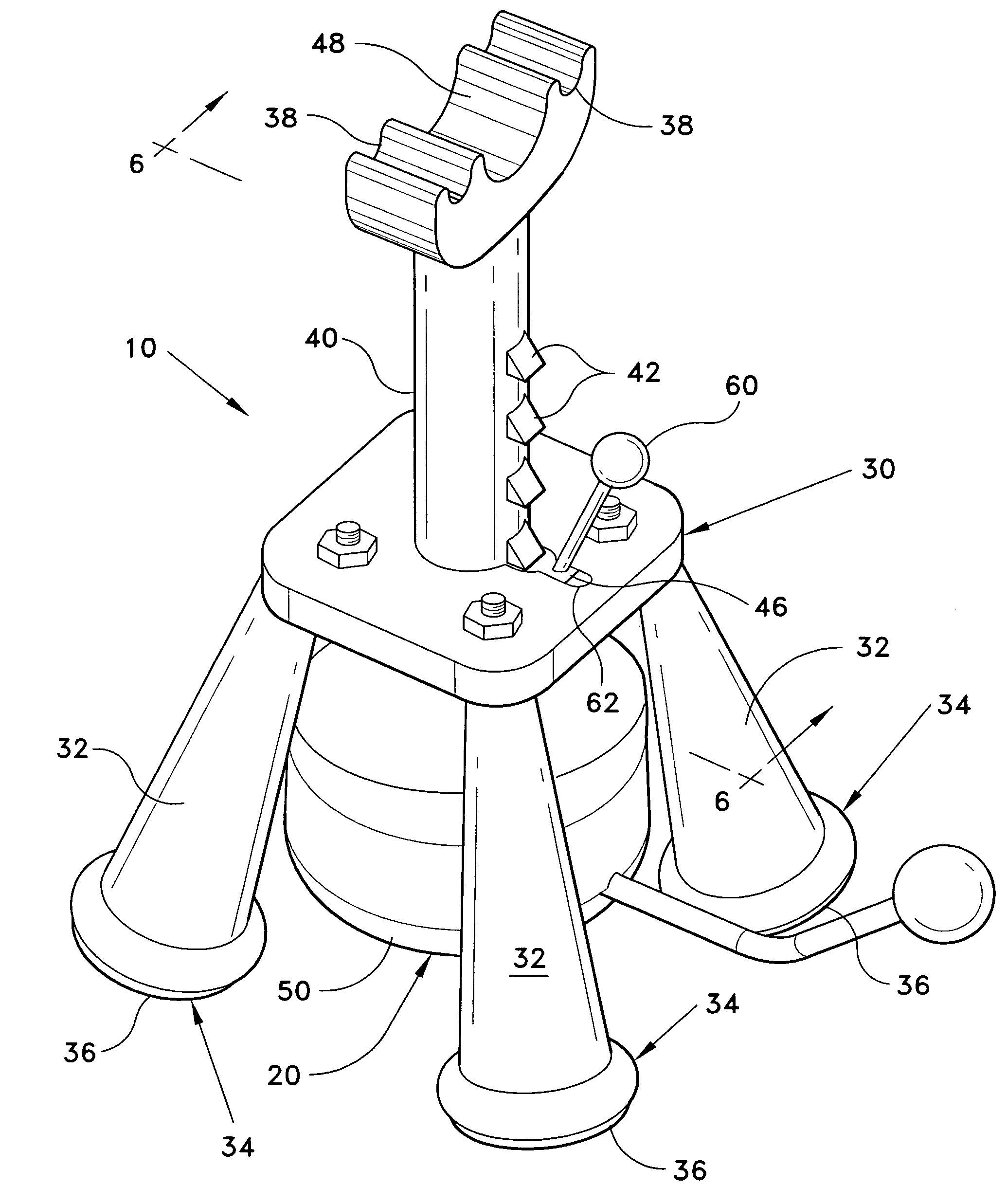
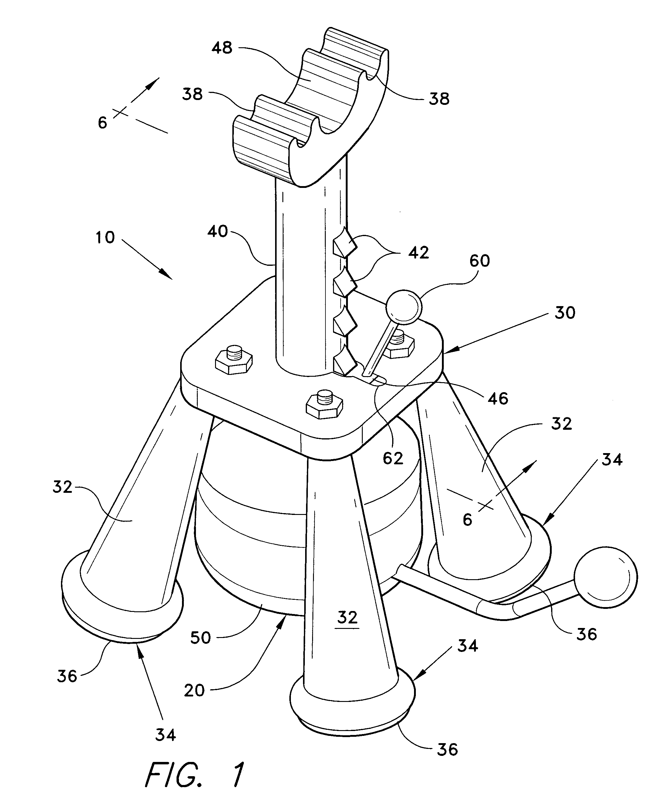
[0022]The present invention is a hydraulic jack stand, designated generally as 10. As shown in FIG. 1, the hydraulic jack stand 10 has a hydraulic jack 20 with an integral jack stand 30. The jack stand 30 helps stabilize and support the heavy object being lifted by the jack 20. By combining the jack stand 30 and a hydraulic jack 20, the user needs only one piece of equipment to raise, support and lower a heavy object such as a vehicle V (see FIG. 5).

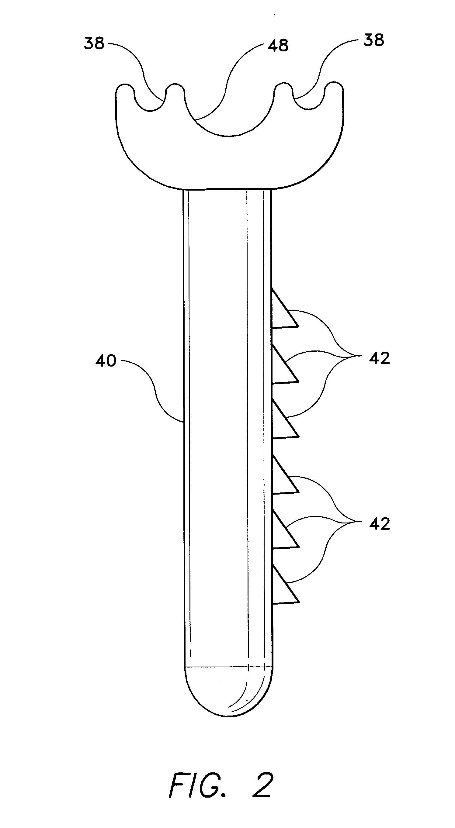
[0023]The hydraulic jack stand 10 uses multiple parallel safety mechanisms to prevent the jack 20 from lowering unexpectedly while being used as a jack stand. The jack 20 uses hydraulic pressure to raise and lower a lifting post 40. Referring to FIG. 4, post 40 fits into an opening 52 in the top of a hydraulic cylinder 50. A handle 22 extends from the hydraulic cylinder 50 and is used to operate the jack 20. By pumping the handle 22, hydraulic fluid is forced into a chamber in cylinder 50, beneath a piston (not shown) under the lifting p...


PUM


Abstract

The hydraulic jack stand is a hydraulic jack with an integral jack stand. The jack stand helps stabilize and support a heavy object being lifted by the jack. The hydraulic jack stand uses multiple parallel safety mechanisms to prevent the jack from lowering unexpectedly while being used as a jack stand. The jack uses hydraulic pressure to raise and lower a lifting post. Pivoting teeth arranged along the lifting post allow the lifting post to be raised while preventing the post from falling due to any failure in the hydraulic cylinder. The jack stand has several legs, which extend out to provide a wide base. The legs have feet with non-slip pads underneath to protect the legs from wear and to help prevent the stand from slipping.

Description

CROSS-REFERENCE TO RELATED APPLICATION[0001]This application claims the benefit of U.S. Provisional Patent Application Ser. No. 60 / 673,799, filed Apr. 22, 2005.BACKGROUND OF THE INVENTION[0002]1. Field of the Invention[0003]The present invention relates to hydraulic jacks and devices used to stabilize hydraulic jacks while supporting a heavy object. More specifically, the device is a hydraulic jack with an integral jack stand.[0004]2. Description of the Related Art[0005]Hydraulic jacks are often used to raise a motor vehicle off the ground, to allow the vehicle to be repaired. However, these jacks lack the stability to maintain the vehicle in that position safely while a person works under the vehicle. Jack stands have been developed to support the vehicle in a stable, safe manner once the vehicle has been raised off the ground. These jack stands usually have a wide support base and do not raise or lower, so that there is little chance of one accidentally failing and allowing the ve...

Claims


Application Information

Patent Timeline
Patent Type & Authority Patents(United States)
IPC IPC(8): B66F3/24
CPCB66F3/30B66F3/36
Inventor PORTER, RODNEY
Owner PORTER RODNEY
Why Eureka
Try Eureka