Bumper with nesting energy-absorbing end piece

a bumper and end piece technology, applied in the direction of bumpers, vehicular safety arrangements, pedestrian/occupant safety arrangements, etc., can solve the problems of inconsistency, variables, and complications in the final components, and achieve the effect of reducing the number of components

Inactive Publication Date: 2006-12-12
SHAPE CORP
View PDF15 Cites 26 Cited by
  • Summary
  • Abstract
  • Description
  • Claims
  • Application Information

AI Technical Summary

Problems solved by technology

This results in conflicting requirements.
However, such processes are expensive, because cutting a high-strength beam is expensive, and also because weldingly attaching a secondary bracket is time consuming, expensive, and leads to inconsistencies, variables, and complications in the final components.

Method used


Image

  • Bumper with nesting energy-absorbing end piece
  • Bumper with nesting energy-absorbing end piece
  • Bumper with nesting energy-absorbing end piece

Examples


Embodiment Construction

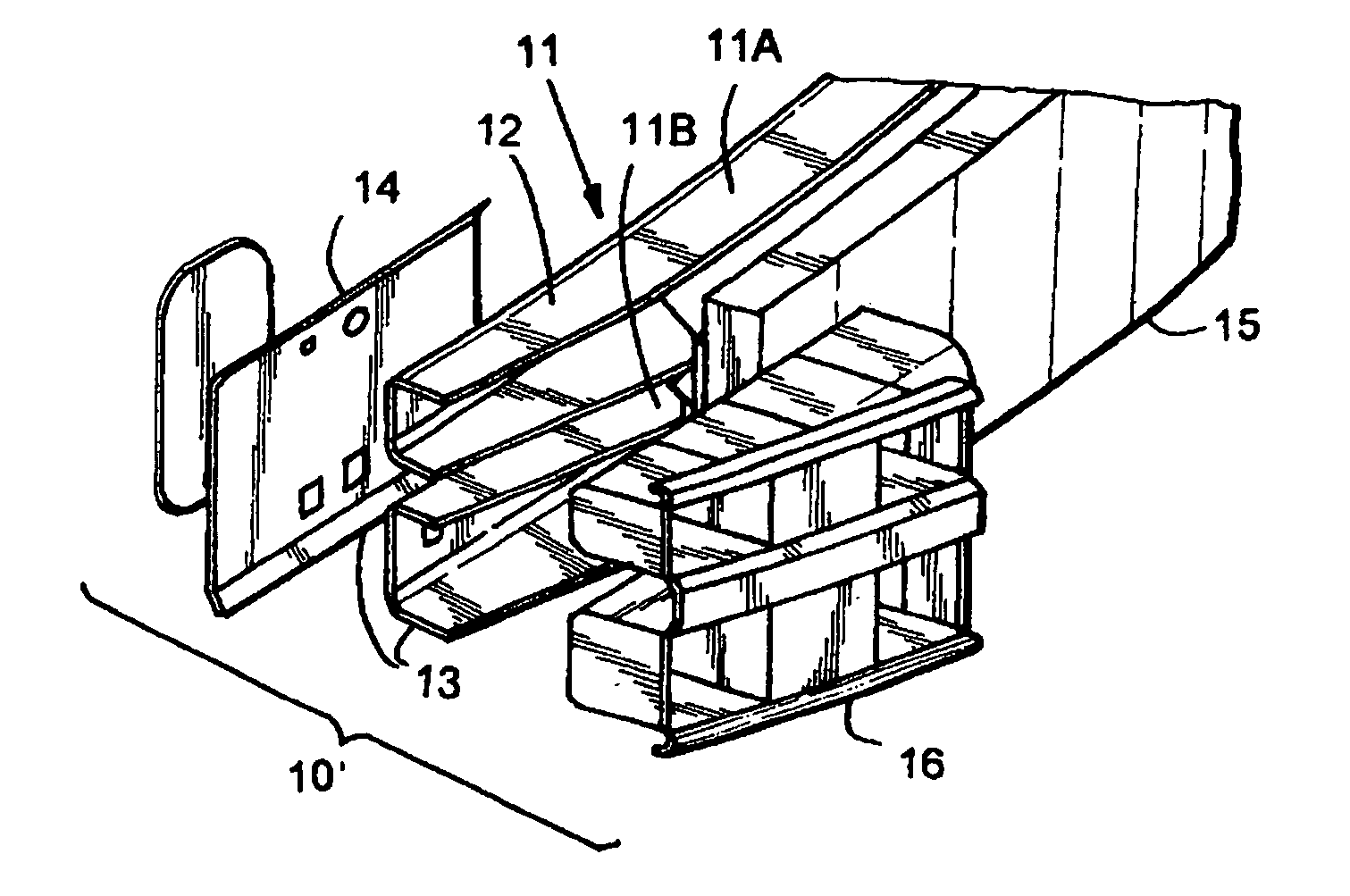
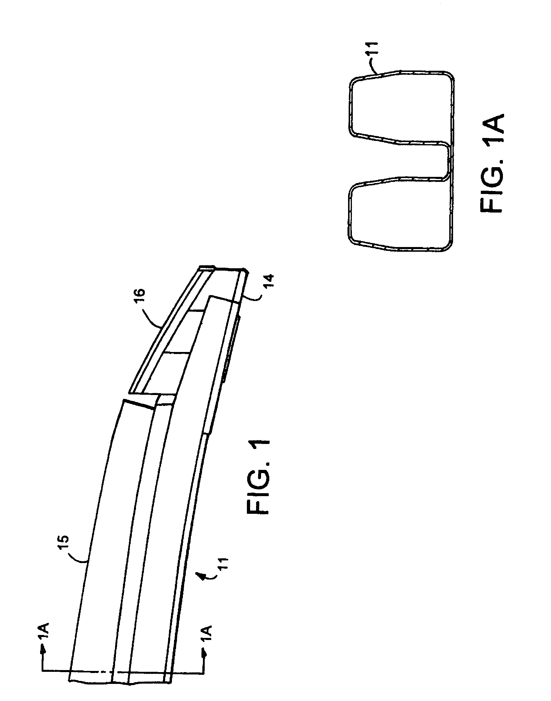
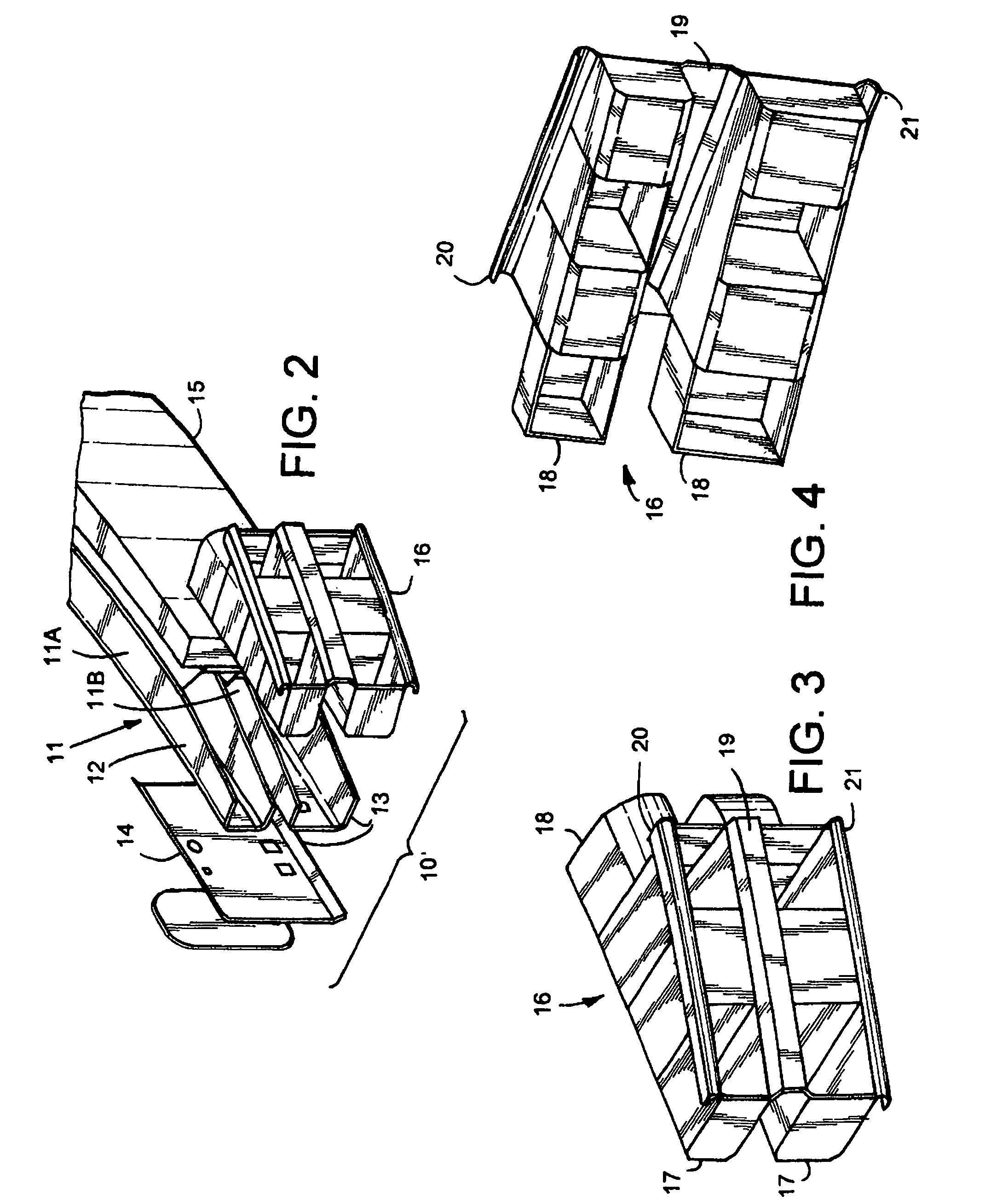
[0012]A bumper system 10 (FIG. 1) includes a high-strength metal B-shaped beam 11 with miter-cut end sections 12, a front center energy absorber 15 against a face of the beam 11, and a pair of energy-absorbing end pieces 16 that nestingly engage front outer ends of the beam 11. By this arrangement, the bumper system 10 with energy absorbers 15–16 forms an impact system capable of providing impact resistance as required by Federal Motor Vehicle Safety Standards of the U.S. government, yet at a reduced cost. In particular, the energy-absorbing end pieces 16 act as a low-cost and lightweight extension to the beam 11, and absorb energy so as to lessen intrusion and decrease the energy that is transmitted into the frame rails.

[0013]The illustrated beam 11 defines two tubes 11A and 11B. (It is contemplated that the present invention could also be used on other beam sections, such as a “D” shaped beam or box beam.) Each end section 12 is miter-cut to have an angled front on its front outer...


PUM


Abstract

A bumper system includes a high-strength metal B-shaped beam with miter-cut end sections, a front center energy absorber, and a pair of energy-absorbing end pieces that nestingly engage front outer ends of the beam. By this arrangement, the bumper system with energy absorbers forms an impact system capable of providing good corner impact resistance. The energy-absorbing end pieces act as a low-cost and lightweight extension to the beam, and absorb energy so as to lessen intrusion and decrease the energy that is transmitted into the frame rails of the vehicle.

Description

CROSS-REFERENCE TO RELATED APPLICATIONS[0001]This application claims benefit of provisional application Ser. No. 60 / 561,737, filed Apr. 13, 2004, entitled BUMPER WITH NESTING ENERGY-ABSORBING END PIECE, the entire contents of which are incorporated herein in their entirety.BACKGROUND[0002]The present invention relates to vehicle bumper systems having energy absorbers, including energy-absorbing end pieces that nest against the bumper beam.[0003]Modern vehicles have bumper systems that are both functional and aesthetic. Functionally, they must be able to withstand substantial impact requirements, including front and corner impact testing standards, such as those set by the insurance and federal agencies. Also, they must meet customer expectations concerning appearance. In particular, many modern vehicles have an aerodynamic appearance, with sweeping curved fronts, especially at vehicle corners. The vehicles are also compact in design. This results in conflicting requirements. On the...

Claims


Application Information

Patent Timeline
Patent Type & Authority Patents(United States)
IPC IPC(8): B60R19/18B60R19/04B60R21/00
CPCB60R19/18B60R19/04B60R2019/1826B60R2019/1866B60R2021/0009E04C2003/0456
Inventor EVANS, DARINWHITE, MARK S.DORNBOS, ROBERT J.WAKEFIELD, WILLIAM A.
Owner SHAPE CORP
Why Eureka
Try Eureka