Dynamic forging impact energy retention machine

a technology of energy retention machine and impact force, which is applied in the field of shock (impact) machines, can solve the problems of large risk, large joint size, unwieldy stands, etc., and achieve the effect of low cost and efficient production of bodies

Inactive Publication Date: 2005-10-06
OLSSON KENT
View PDF7 Cites 20 Cited by
  • Summary
  • Abstract
  • Description
  • Claims
  • Application Information

AI Technical Summary

Benefits of technology

[0031] The object of the present invention is to design an impact machine which achieves a low cost process for efficient production of bodies from a particulate material or a solid material by coalescence or compaction to a higher density.
[0032] Another object is to achieve a design of the machine for optimised production of material bodies to a higher density and to reduce the required shock energy with the objective to reduce the loading of machine and tool parts. And, also to manufacture components of better material properties and higher quality. Furthermore, the aim is to design the machine so that it can easily be adapted to manufacture a wide range of different component sizes, shapes and material types. SHORT DESCRIPTION OF THE INVENTION

Problems solved by technology

The stress on all joints therefore become very large, as well as on sensitive components, e.g. electronic components for controlling those hydraulic valves which usually form parts of impact machines, which may cause a great risk, of failure.
Large, unwieldy stands also give rise to problems in connection with service, change of tool unit or of tool inserts in the tool unit, changing the height of the impact unit above the tool unit.
Furthermore, moving the machine from one site to another with a fixed foundation is very complicated and costly.
This is not possible with the machine principles of prior art.
Re-bouncing creates cracks and results in micro-fractures of the produced body.
From practical tests the theoretical model described in WO 97 / 00751, does not work, as the body cracks and gets micro-fractures.
Additionally, the example describes a process which is today physically impossible to perform and to design a working machine for.
In this case, high strain and stress variations are induced during the impact, and the sudden release of the shock load, which results in a minor explosion due to built-up of residual stress and strain.
Furthermore, to obtain material body densities close to the theoretical density of many metal, ceramic and polymer materials, these machines require high shock, stroke or impact energies resulting in short tool life span and high tool costs, due to load exhaustion and short-term fatigue.
The tool carrier system including a multiple of identical tools for manufacturing of a component suggested in the machine described in patent WO 02 / 22289, is assumed to be practically economically impossible due to high tool costs.
Another problem with known impact machines of the aforesaid type is that they have a comparatively small production capacity.
This is basically due to the clumsiness of the machines, which makes it difficult to provide the machine with devices which would make a rational production possible.
The strokes according to the method described in WO-A1-9700751, give a locally very high temperature increase in the material, which can lead to phase changes in the material during the heating or cooling.
It has now been found that the machine according to these documents does not work so well.
For example, the time intervals between the strokes, which they mention, are not possible to attain.
Also, the rebounding strokes have proved to result in cracking of the material.

Method used


Image

  • Dynamic forging impact energy retention machine
  • Dynamic forging impact energy retention machine
  • Dynamic forging impact energy retention machine

Examples


example 1

[0178] This example illustrates the superiority of the DFIER machine comprising an inner static press system and an outer impact system of a single side acting ram configuration compared to a single outer impact system alone as described for the percussion machine in patent WO 97 / 00751, the so called first generation machines.

[0179] The DFIER machine configuration comprising an upper inner press system including a central unit, an upper outer impact system, and a stationary anvil. The central unit is a carrier for a moulding die with a through hole. The anvil positioned below the central unit provides as a support for the lower punch positioned on the anvil. The inner system comprises a press unit including a ram housing, a press ram and a upper punch as well as a vibration unit. The press ram housing is open in both ends so that the press ram is protruding from the ram housing at both the upper and lower end. The said press ram is acting vertically and positioned above the central...

example 2

[0192] This example illustrates the superiority of having an inner and an outer system compared to an outer system alone with a counter-acting ram configuration, compared to an outer impact system alone with a counter-acting impact ram configuration as described for the impact machine described in patent WO 02 / 22289.

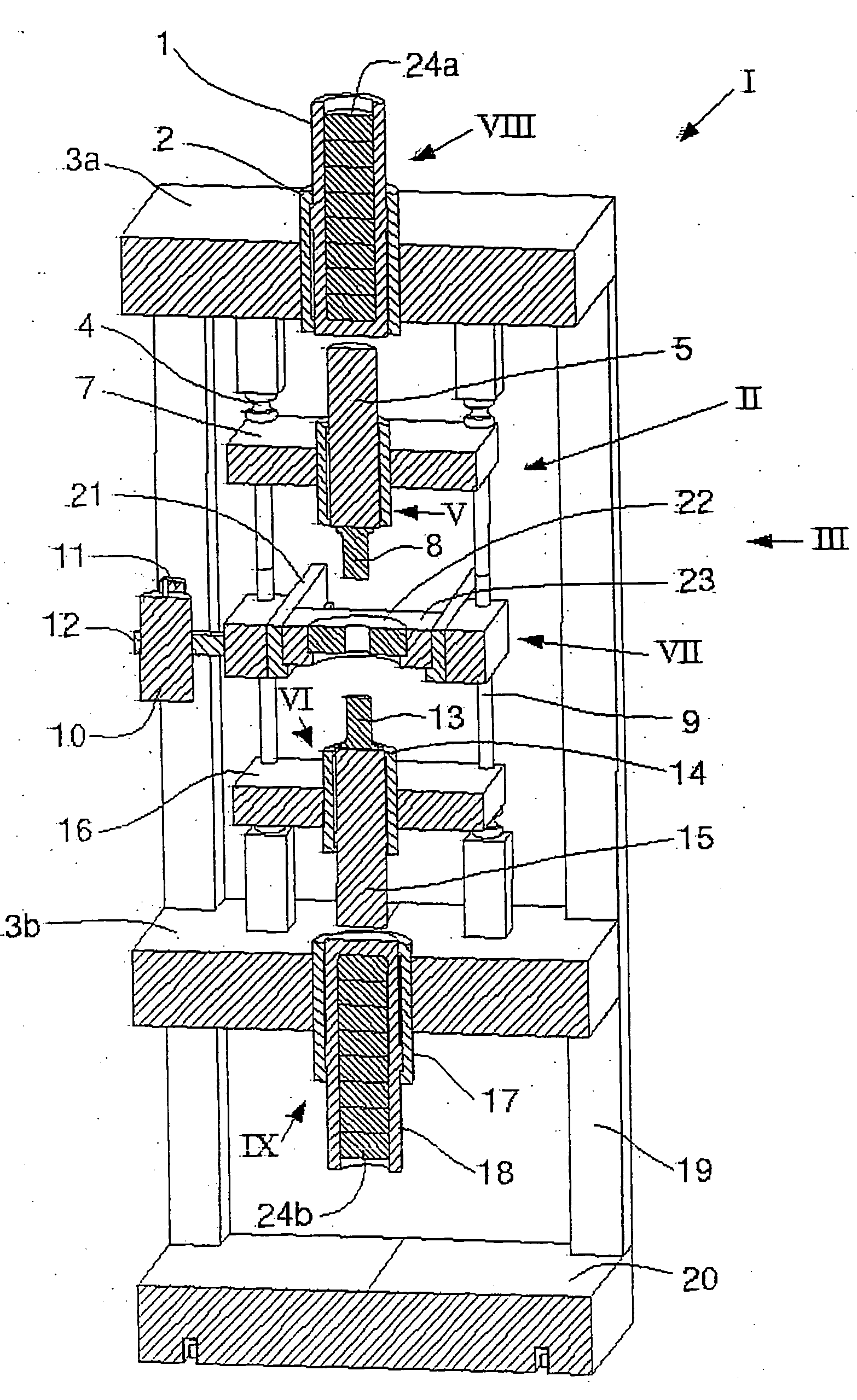
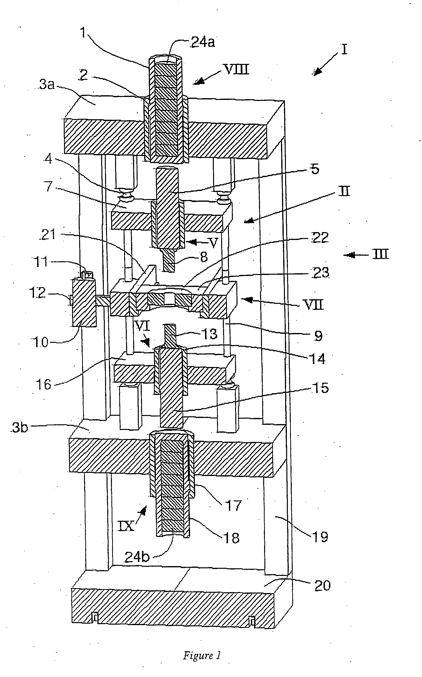
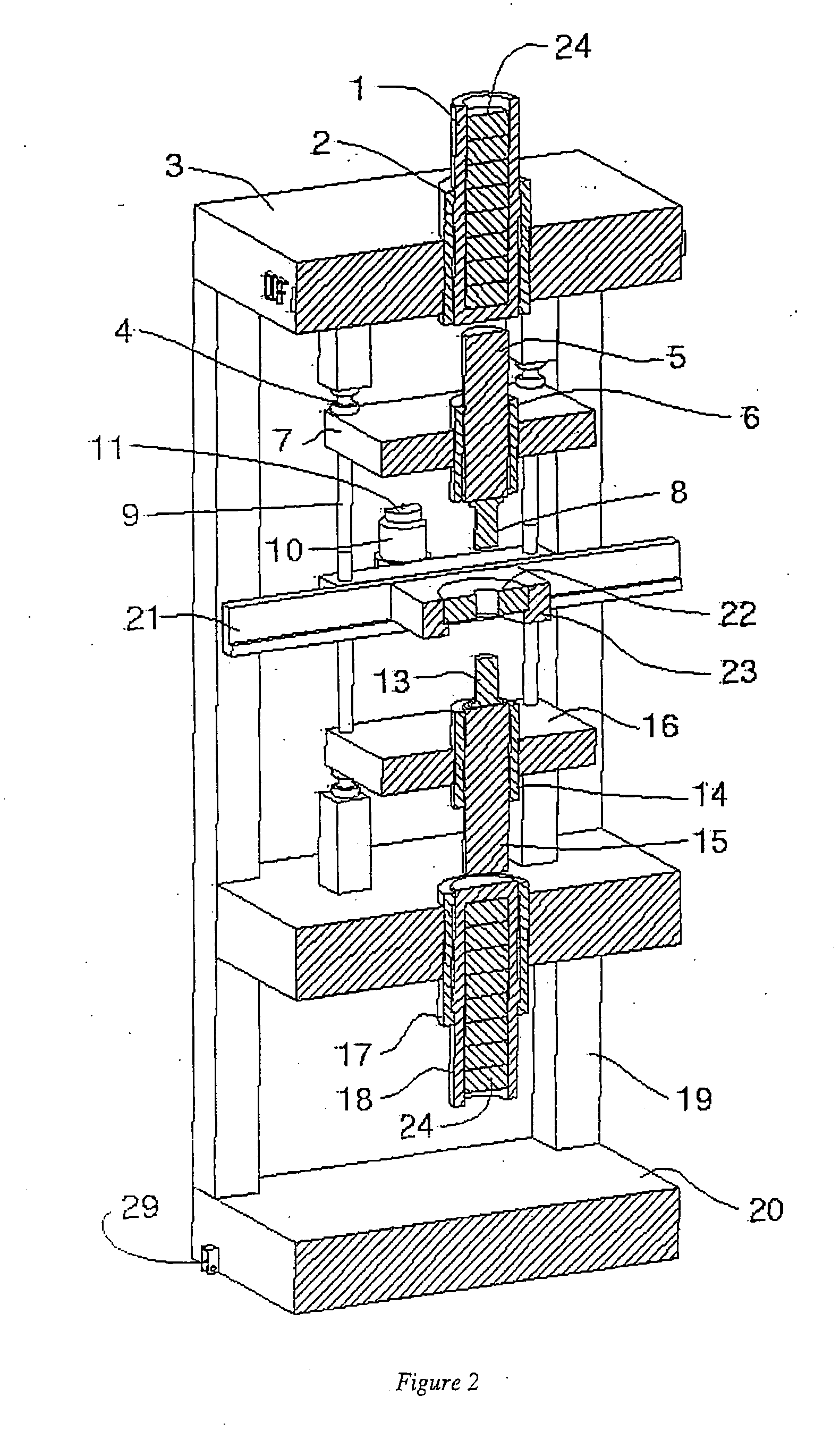
[0193] The DFIER machine comprises an inner press system, and an outer impact system. The inner system comprises an upper press unit, a lower counter-acting press unit, a central unit and a vibrator system. The upper press unit comprises an upper ram housing, an upper press ram and an upper punch attached to the upper press ram. The lower press unit comprises a lower ram housing, a lower press ram and a lower punch attached to the lower press ram. The central unit is positioned between the upper and the lower press units, and carries a moulding die with a protruding hole. The upper and lower press ram housings are opened in both ends so that the press rams are protrudin...

example 3

[0210] Comparing the single side action configuration with the counter acting machine configurations, the counter acting configuration is superior the single side configuration and the differences are summarised as: [0211] large and costly foundations are obsolete due to the force vector balance between the counter acting systems [0212] the energy fraction transferred to the material powder is much higher is the counter acting configuration due the the force balance and the two counter moving shock waves, whereas the shock wave from the single side configuration is transferred through the working material and out in the tool members [0213] the tool life span is increased with a counter acting configuration, due to the reduced required shock energy, resulting in lower production costs.


PUM

PropertyMeasurementUnit
shapeaaaaaaaaaa
densityaaaaaaaaaa
velocityaaaaaaaaaa

Abstract

A machine for producing a body with desired shape of a workable material through dynamic forging under impact and finally with energy retention while the shock wave fades out. The machine includes a machine stand, a dynamic outer impact system having an upper unit, and a lower impact unit, which includes a counter-impact device, and possibly one or more dynamic side impact units, and a static inner press system having an upper unit and a lower unit, possibly with additional one or more static side compacting units, with a central unit in between. The lower units of the outer and inner systems can be exchanged with a common stationary anvil for a single direction machine instead of a counter-acting machine.

Description

TECHNICAL FIELD [0001] The invention concerns a shock (impact) machine, performing Dynamic Forging Impact Energy Retention (DFIER), for forming a body with desired shape of a workable material through shock (impact) action in an impact step, said impact machine comprising a machine stand, a dynamic outer system and a static inner system. Two embodiments are here exemplified; First, an embodiment where action is performed without a stationary anvil, comprising an inner system, which comprises an upper press unit with a ram and a punch, a flower press unit which comprises a counter-acting ram and a punch, and an outer system, comprising an upper impact ram unit and a lower counter-acting impact ram unit, each comprising mountable weights. Second, an embodiment where action is performed with a stationary anvil, comprising an inner system, which comprises an upper press unit with a ram and a punch, and an outer system comprising an upper impact ram unit, comprising mountable weights, wi...

Claims


Application Information

Patent Timeline
Patent Type & Authority Applications(United States)
IPC IPC(8): B21J7/02B21J7/28B22F3/087B30B11/02B21J7/34
CPCB21J7/02B21J7/28B21J7/34B22F3/087B22F2003/033B22F2999/00B29C2043/3618B30B11/027B22F3/14B22F3/105B30B11/022
Inventor OLSSON, KENT
Owner OLSSON KENT
Why Eureka
Try Eureka