
Control System For Modulating Water Heater

a control system and water heater technology, applied in fluid heaters, lighting and heating apparatus, heating types, etc., can solve problems such as undesirable swings in system temperature, on and off cycle of boilers, and fluctuation of water flow rate in primary heating loops, so as to reduce the cycle of modulating water heaters. , the effect of preventing condensation of water vapor

Active Publication Date: 2009-03-12
LOCHINVAR
View PDF25 Cites 18 Cited by
  • Summary
  • Abstract
  • Description
  • Claims
  • Application Information

AI Technical Summary

Benefits of technology

"The present invention provides a control system for modulating water heaters that reduces cycling of the heaters, especially in systems with multiple boilers. The control system addresses issues such as wear and tear on the boilers, changes in flow rate, and condensation of water vapor in exhaust flue gasses. By monitoring and controlling the flow rate, temperature, and exhaust gas temperature, the system can use more economical materials and avoid common exhaust flues for multiple boilers. The control system also allows early detection of changes in system heat load and prevents condensation of water vapor. Overall, the control system improves the efficiency and reliability of modulating water heaters."

Problems solved by technology

One challenge encountered with a system of modulating boilers like that just described is to minimize the cycling on and off of each boiler.
This zone, which may be referred to as a deadband or dead zone, presents unique operational problems because the second boiler cannot modulate within that range.
Another issue encountered in commercial heating systems is that the flow rate of the water in the primary heating loop can change frequently and by a significant amount as heating zones are turned on and off.
As this flow changes, the heat load on the system typically changes with it.
But the change in system temperature lags significantly in time behind the change in flow rate, and causes undesirable swings in system temperature and on and off cycling of the boiler as the boiler control system attempts to correct for the change in temperature.

Method used


Image

  • Control System For Modulating Water Heater
  • Control System For Modulating Water Heater
  • Control System For Modulating Water Heater

Examples


Embodiment Construction

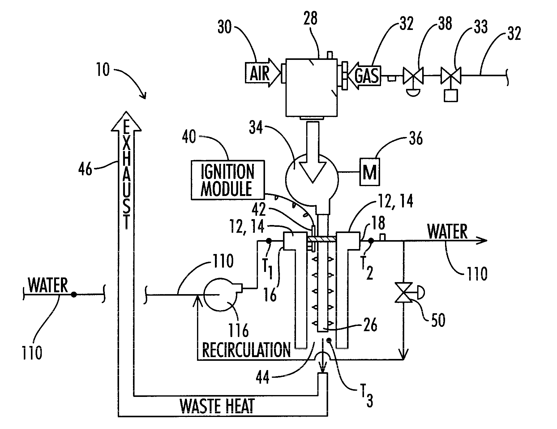
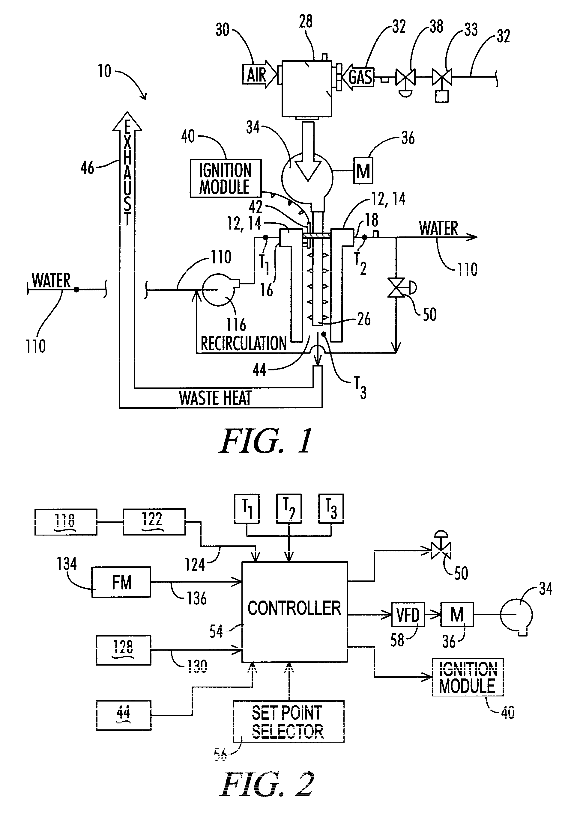
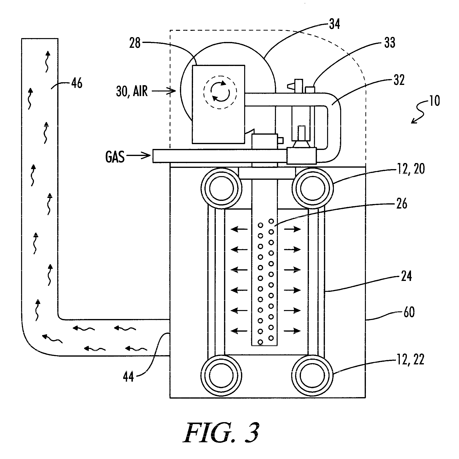
[0030]Referring now to the drawings, and particularly to FIG. 1, the water heater or boiler apparatus of the present invention is shown and generally designated by the numeral 10. As used herein, the term water heater refers to an apparatus for heating water, including both steam boilers and water heaters that do not actually “boil” the water. Much of this discussion refers to the apparatus 10 as a boiler 10, but it will be understood that this description is equally applicable to water heaters that do not boil the water. The boiler 10 includes a heat exchanger 12 having a water side 14 having a water inlet 16 and a water outlet 18.

[0031]The general construction of the heat exchanger 12 may be similar to that disclosed for example in U.S. Pat. No. 4,793,800 to Vallett et al., or that in U.S. Pat. No. 6,694,926 to Baese et al., the details of which are incorporated herein by reference. As illustrated in FIGS. 2, 8 and 9 of Vallett et al., the heat exchanger is a multiple pass exchang...


PUM


Abstract

A control system is provided for a modulated heating system including at least one modulating water heater and a controller. A deadband control scheme provides for reduced cycling of the modulating heater when total system heat demand falls between the maximum output of one heater and the sum of the maximum output of that one point and the minimum firing point of the next subsequent heater. Condensation of flue gas products is prevented by monitoring flue exhaust temperature for each heater and controlling the modulation of each heater to maintain a minimum heater output sufficiently high to prevent condensation of flue gas products from that heater. Rapid reaction to changes in system heat demand is provided by sensing changes in flow rate in a primary loop of the system and anticipating resulting changes in temperature thus allowing for change in heater output prior to the time the change in flow rate has fully impacted system temperature.

Description

[0001]I, John C. Paine, a citizen of the United States, residing at Brentwood, Tenn.; have invented a new and useful “Control System For Modulating Water Heater.” The present application is a divisional application of U.S. patent application Ser. No. 11 / 684,049 of John C. Paine filed Mar. 9, 2007, the details of which are incorporated herein by reference.BACKGROUND OF THE INVENTION[0002]1. Field of the Invention[0003]The present invention relates generally to water heaters and boilers, and more particularly, but not by way of limitation, to a control system for a modulating water heater or boiler which is particularly constructed for use as one of a plurality of water heaters or boilers controlled in a cascading sequence.[0004]2. Description of the Prior Art[0005]Conventional water heater technology utilizes a burner designed to operate at a fixed flow rate of combustion air and fuel gas to the burner. Such a water heater cycles on and off in response to a control system which monit...

Claims


Application Information

Patent Timeline
Patent Type & Authority Applications(United States)
IPC IPC(8): F24H9/20F24H9/00
CPCF23N1/082F23N2041/04Y02B30/108F24D2200/043F24D19/1009F24H9/2035F23N2241/04F24H15/219F24H15/34F24H15/215F24H15/238F24H15/174F24H15/36F24H15/35F24H15/235Y02B30/00
Inventor PAINE, JOHN C.
Owner LOCHINVAR
Learn More