Reference voltage generation circuit, and constant voltage circuit using the reference voltage generation circuit

a reference voltage generation circuit and reference voltage technology, applied in the direction of electrical equipment, semiconductor devices, instruments, etc., can solve the problems of large variation worse temperature characteristics, and worse initial accuracy of reference voltage vref, so as to reduce temperature fluctuation and power source fluctuation, the effect of reducing the fluctuation of output voltag

Inactive Publication Date: 2007-03-15
RICOH ELECTRONIC DEVICES CO LTD
View PDF5 Cites 3 Cited by
  • Summary
  • Abstract
  • Description
  • Claims
  • Application Information

AI Technical Summary

Benefits of technology

[0044] According to the reference voltage generation circuit and the constant voltage circuit using the reference voltage generation circuit of the present invention, as to initial accuracy of the reference voltage generated by the reference voltage generation circuit, it is improved from ±30% to ±6%. The temperature characteristic is improved from 300 ppm / ° C to 40 ppm / ° C. In addition, fluctuation of the reference voltage Vref against power source voltage fluctuation is decreased to no more than 1 / 10. Thus, variations of the reference voltage due to process fluctuation, temperature fluctuation and power source fluctuation can be reduced. In addition, as to the constant voltage circuit, fluctuation of the output voltage can be reduced.

Problems solved by technology

Since the two kinds of the transistors of the depletion-type and the enhancement-type are used, the threshold voltage Vth of each transistor fluctuates independently due to process fluctuation, so that initial accuracy of the reference voltage Vref becomes worse.
Thus, there is a problem in that variation of the reference voltage Vref is large.
Therefore, the temperature characteristic becomes worse.
Accordingly, there is a problem in that the temperature characteristic of the reference voltage Vref is large.
But, since the circuit uses a resistance as a constant current source, the third problem cannot be solved.

Method used


Image

  • Reference voltage generation circuit, and constant voltage circuit using the reference voltage generation circuit
  • Reference voltage generation circuit, and constant voltage circuit using the reference voltage generation circuit
  • Reference voltage generation circuit, and constant voltage circuit using the reference voltage generation circuit

Examples


first embodiment

(First embodiment) FIG. 7 shows an example of a reference voltage generation circuit in the present invention.

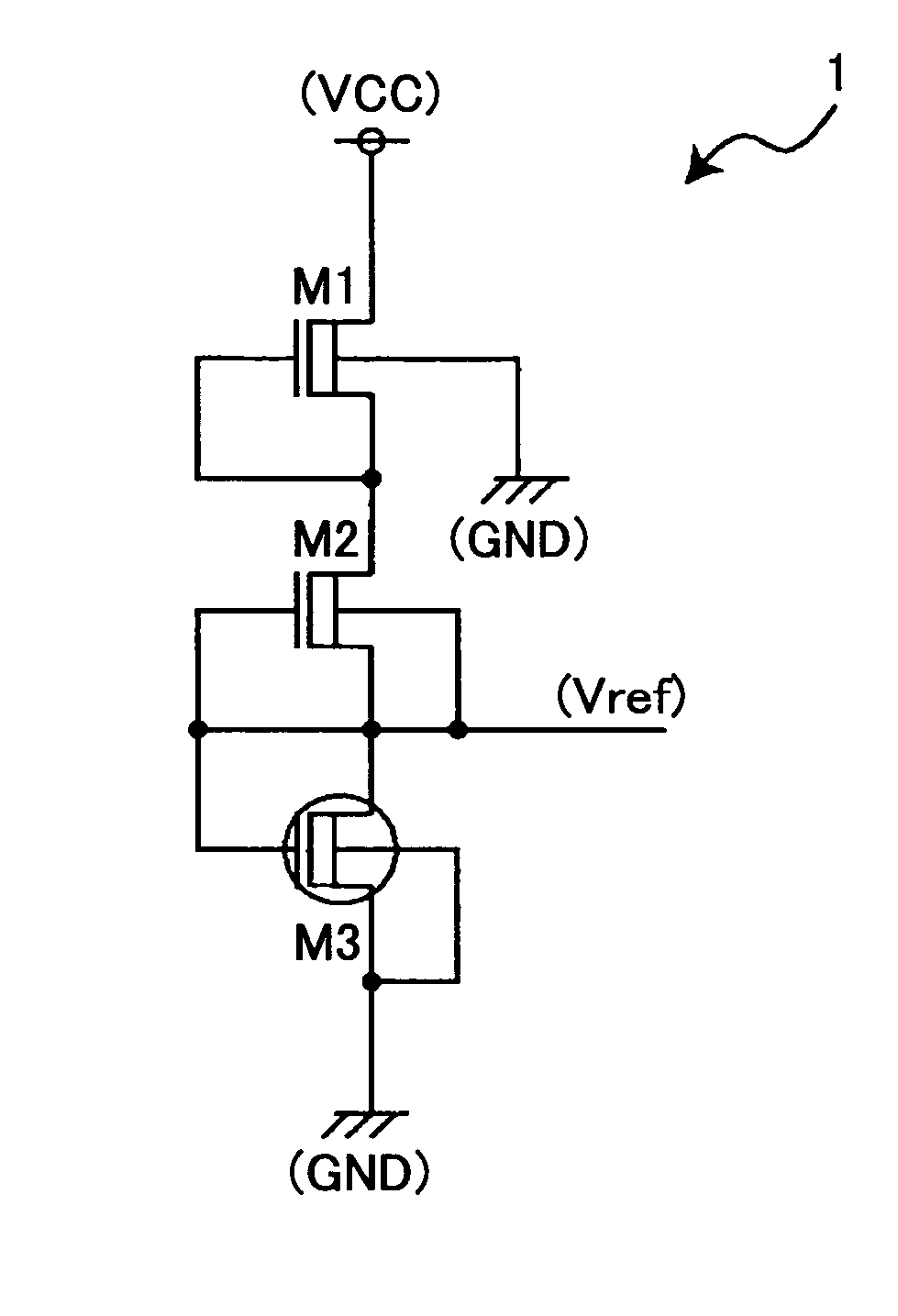
[0063] In FIG. 7, the reference voltage generation circuit 1 includes a n channel-type field-effect transistors M1-M3 which are serially connected between a power source voltage VCC and a ground voltage GND. The field-effect transistor Ml corresponds to a first field-effect transistor, the field-effect transistor M2 corresponds to a second field-effect transistor, and the field-effect transistor M3 corresponds to a third field-effect transistor.

[0064] The field-effect transistor Ml is a depletion-type transistor that is formed in a p well of a n-type substrate. In the field-effect transistor Ml, a gate and a source are connected, and a substrate gate is connected to the ground voltage GND. As to the field-effect transistors M2 and M3, impurity densities of substrates and channel dope are the same. Each of the field-effect transistors M2 and M3 is formed in a p well of a n-t...

second embodiment

(Second embodiment)

[0095] In the first embodiment, the substrate gate of the field-effect transistor M2 is connected to the source of the field-effect transistor M2. But, the substrate gate of the field-effect transistor M2 can be connected to the ground voltage GND. This configuration is described as the second embodiment of the present invention.

[0096]FIG. 15 shows an example of a reference voltage generation circuit in the second embodiment of the present invention. In FIG. 15, the same features as those of FIG. 7 are indicated with the same reference signs. In the following, different points from FIG. 7 are mainly described.

[0097] In the circuit shown in FIG. 15, the different point compared to FIG. 15 is that the substrate gate of the field-effect transistor M2 is connected to the ground voltage GND.

[0098] In such configuration, in the same way as the circuit shown in FIG. 7, when impurity density of the substrate or channel dope fluctuates due to process fluctuation, each d...


PUM


Abstract

A reference voltage generation circuit includes: a first field-effect transistor that is an n channel-type field-effect transistor of a depletion-type, wherein one terminal of the first field-effect transistor is connected to a predetermined power source voltage; a second field-effect transistor including a concentrated n-type gate, wherein one terminal of the second field-effect transistor is connected to another terminal of the first field-effect transistor; and a third field-effect transistor including a concentrated p-type gate, wherein one terminal of the third field-effect transistor is connected to another terminal of the second field-effect transistor; wherein a gate of the first field-effect transistor is connected to a part where the first and the second field-effect transistors are connected, each substrate gate of the first and the third field-effect transistors is connected to a ground voltage, a gate and a substrate gate of the second field-effect transistor and a gate of the third field-effect transistor are connected to a connecting part where the second and the third field-effect transistors are connected, and a reference voltage is output from the connecting part.

Description

BACKGROUND OF THE INVENTION [0001] 1. Field of the Invention [0002] The present invention relates to a reference voltage generation circuit and a constant voltage circuit using the reference voltage generation circuit. More particularly, the present invention relates to a reference voltage generation circuit using a principle of a work function difference between gate electrodes of two field-effect transistors, and to a constant voltage circuit using the reference voltage generation circuit. [0003] 2. Description of the Related Art [0004]FIG. 1 shows a conventional reference voltage generation circuit (refer to Japanese publication of examined application No. 4-65546, for example). In the reference voltage generation circuit, a depletion-type field-effect transistor and an enhancement-type field-effect transistor are serially connected, and a difference between threshold voltages (Vth) of these field-effect transistors is extracted as a reference voltage Vref. [0005] In FIG. 1, a tr...

Claims


Application Information

Patent Timeline
Patent Type & Authority Applications(United States)
IPC IPC(8): H01L29/76
CPCG11C5/147
Inventor AOTA, HIDEYUKI
Owner RICOH ELECTRONIC DEVICES CO LTD
Why Eureka
Try Eureka